


A welding cable size chart tells you the smallest conductor that will carry your welder’s output current over your actual lead length without overheating or dropping too much voltage. Three variables decide it: output amperage, the total length of both leads, and the duty cycle the machine runs at.
The short version: start from the amperage your machine actually welds at, add the electrode lead and the work lead together to get total circuit length, then move up a size for every stage of added length. A 300 A machine on a 50-foot total circuit and a 300 A machine on a 200-foot circuit are not the same specification, and treating them as one is the most common and most expensive sizing mistake on a shop floor.
Most charts you will find give you a grid of numbers and stop there. The numbers are only valid under conditions that almost nobody prints. This guide gives you the figures, and then tells you what they assume — because a chart applied outside its assumptions is worse than no chart at all.
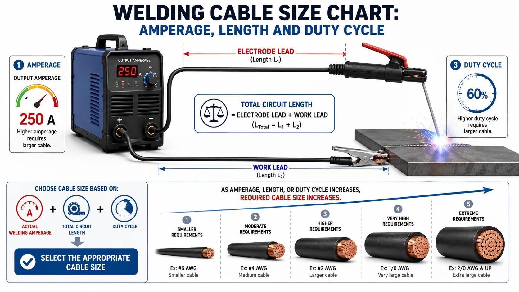
What size welding cable do I need?
Welding cable size is chosen by matching conductor ampacity to the welder’s output current, then increasing the size to compensate for total lead length and duty cycle. At a copper temperature of 60 °C and an ambient of 40 °C, 2 AWG carries about 150 A and 4/0 AWG about 315 A on a 60 % duty cycle.
Those ampacity values, published by distributor IEWC, are the base case. The table below pairs them with the application each size actually suits, so the decision is not purely numerical.
| Size | Ampacity | Choose this when |
|---|---|---|
| 2 AWG | 150 A | Light to medium fabrication, short leads under roughly 50 ft total, machines up to about 150 A |
| 1 AWG | 170 A | The same duty as 2 AWG but with lead length pushing past 50 ft |
| 1/0 AWG | 200 A | General shop stick and MIG work at 200 A, or 150 A machines on long leads |
| 2/0 AWG | 235 A | Heavier structural work, or 200 A machines where leads run beyond 100 ft |
| 3/0 AWG | 275 A | High-output machines, extended reach across a bay or a yard |
| 4/0 AWG | 315 A | Sustained high-amperage work, long circuits, automated and multi-operator setups |
If your machine’s plate current sits between two rows, take the larger size. Conductors run cooler, voltage drop falls, and the cable survives handling longer. Undersizing costs more in replacement leads than the copper you saved.
What does a welding cable size chart actually assume?
Published charts rest on four conditions that are rarely stated: a specific conductor temperature, a specific ambient temperature, a duty cycle, and an allowable voltage drop. The IEWC figures above assume 60 °C conductor, 40 °C ambient and 60 % duty cycle. Change any one and the safe current changes with it.
This matters more than it sounds. Two well-known charts can disagree by a full cable size for the same amperage, and neither is wrong — they simply assumed different conditions. Before you use any welding cable ampacity chart, find its stated basis. If it does not state one, treat its numbers as indicative and confirm against a source that does.
One more restriction is easy to miss. Length-based sizing tables of the kind Direct Wire publishes are derived for the secondary circuit only, on a 4-volt drop allowance. They are explicitly not for 600 V applications. Using a welding lead chart to size a primary supply conductor is a code and safety error, not a conservative shortcut.
How does cable length change the size you need?
Longer circuits mean more resistance, more voltage drop, and less usable arc voltage at the work. Sizing tables handle this by requiring a larger conductor as total length grows: a machine that needs 2 AWG at 50 feet can need 2/0 or larger once the circuit reaches 150 feet at the same current.
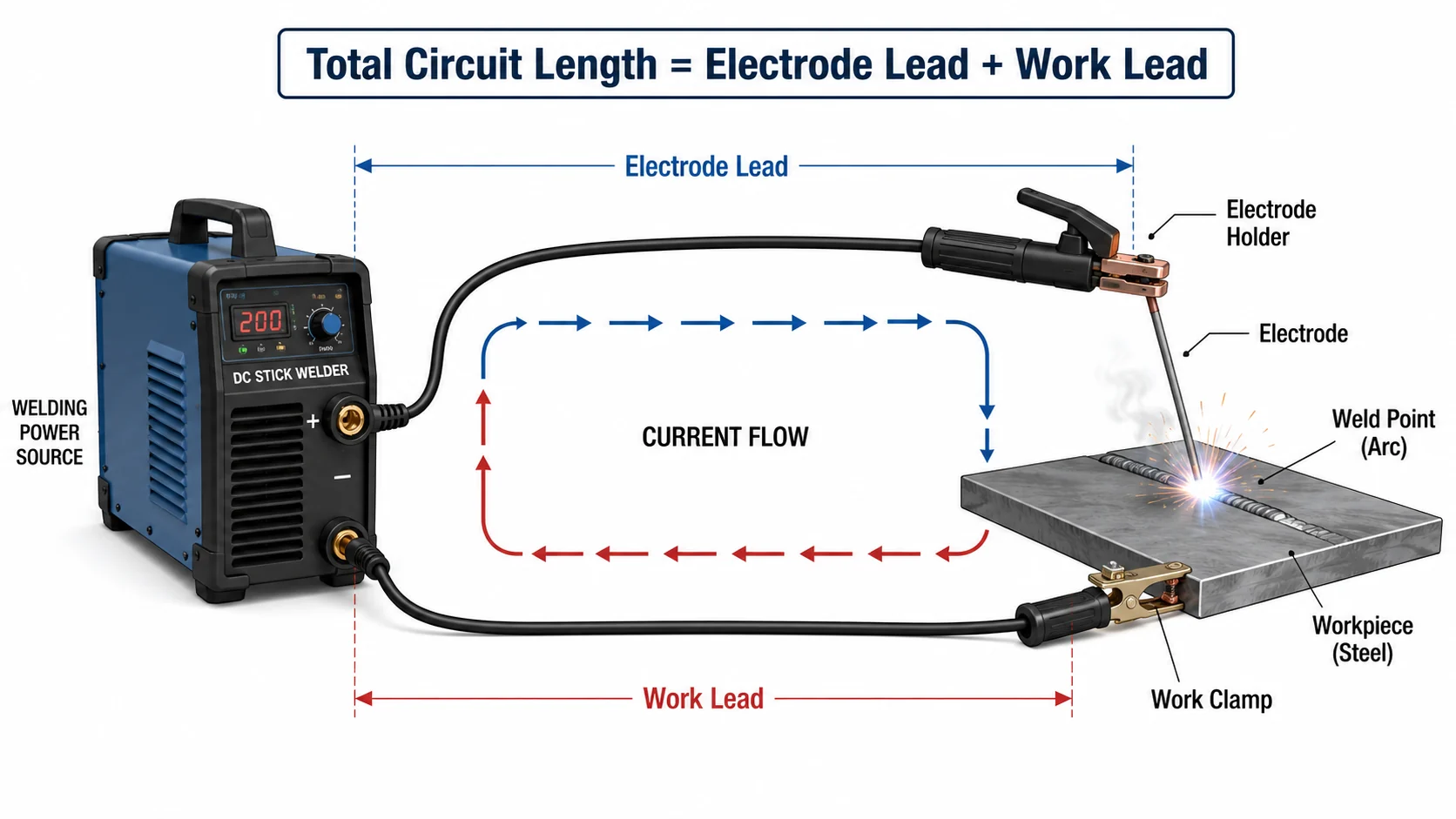
Measure the total circuit, not the reel. Add the electrode lead and the work lead together. A 75-foot electrode lead with a 75-foot work lead is a 150-foot circuit, and sizing it as 75 feet will leave the operator chasing a wandering arc and blaming the machine.
The failure is gradual, which is why it goes unnoticed. Voltage drop does not trip anything. It shows up as poor starts, inconsistent penetration, and an operator quietly turning the amperage up to compensate — which loads the undersized cable further.
How does duty cycle change the size you need?
Duty cycle is the share of a ten-minute period a machine can weld at a given output without exceeding its thermal limit. It changes conductor sizing directly: NEC Article 630 sets ampacity for welder circuits using multipliers from Table 630.31(A)(2), applied to the rated current for the duty cycle the machine actually runs.
The practical consequence is that two shops with identical machines can need different cable. A 300 A machine at 60 % duty cycle in a production cell and the same machine at 20 % duty cycle in a maintenance bay do not present the same thermal load to the lead.
Charts typically publish a single duty-cycle assumption — commonly 60 %. If your operation runs harder than the chart assumes, the chart is optimistic. For fixed installations, size to Article 630 rather than to a marketing table, and have the installing electrician confirm the multiplier against the machine’s nameplate.
What is UL 1276, and does it apply to your cable?
UL 1276 is the North American standard for welding cable. It covers single-conductor 8 AWG through 500 kcmil intended for the secondary circuits of electric welders under NEC Article 630, rated 60, 75, 90 or 105 °C at 100 or 600 volts. It defines what the cable is, not how large yours should be.
There is an important limit on it. UL Listed welding cable meeting UL 1276 is not approved for use as fixed wiring or as general-purpose portable cord unless it carries an additional Listing for that use. Welding cable is flexible, tough and abrasion resistant, which makes it tempting for jobs it was never listed for. Temptation is not a Listing. Where the run genuinely needs general-purpose portable cord rather than a welding lead, that is the job UL 62 cord types are built for — SJOOW 300 V junior-service cord at the lighter end, SOOW at 600 V above it.
When you specify, separate three questions: which standard the construction is built to, which Listings the specific part number actually holds, and which of those the authority having jurisdiction will accept. Ask for the certificate number and its scope rather than a logo on a datasheet.
Sizing mistakes that cost the most
- Sizing on one lead. The circuit is both leads. Halving the length doubles the error.
- Using the machine’s maximum rating. Size for the current you weld at, then check the machine’s rated output — not the top of the dial you never reach.
- Ignoring duty cycle. A 60 % chart applied to continuous production work is optimistic.
- Reusing a secondary-circuit table for primary wiring. Different circuit, different rules, different code section.
- Matching by outside diameter. Jacket thickness and strand class vary; two cables of the same diameter can differ in copper area.
- Forgetting connector and clamp losses. A correctly sized lead with a corroded lug still drops voltage.
Buying questions this raises
Once the size is settled, the specification becomes a purchasing question. Three come up on nearly every enquiry.
How much do I have to order? TEBAOFLEX applies a minimum order quantity of 50 m, and that figure applies to custom constructions as well as standard lines, as of August 2026. Pricing varies with quantity.
How long will it take? Standard lead times run 7 to 45 working days as of August 2026, depending on product type, stock position and customisation. Confirm the current window with the sales team before committing it to a shutdown schedule.
Can I check it before committing? Samples are provided free of charge, with shipping paid by the customer. Where a project needs its own identity, TEBAOFLEX offers OEM and ODM service, including printing your company details on the cable sheath, the drums and the packaging.
Questions this guide cannot answer — approvals for a specific market, jacket compound for a specific chemical exposure, or a construction outside the standard range — go to the engineering team rather than a chart.
Frequently asked questions
Is welding cable the same as battery cable?
Welding cable and battery cable are built differently despite similar appearances. Welding cable uses fine-strand copper for repeated flexing and a rubber-family jacket for abrasion and heat resistance. Battery cable is typically coarser stranded and specified for a fixed installation. Substituting one for the other changes both flexibility and listed suitability.
Can I use a welding cable size chart for the primary supply?
No. Length-based welding cable tables are derived for the welder’s secondary circuit on a limited voltage-drop allowance, and publishers state they must not be used for 600 V applications. Primary supply conductors are sized under the relevant NEC articles for that circuit, not from a welding lead chart.
Does a bigger cable ever cause a problem?
Oversizing costs money, weight and handling comfort rather than performance. Beyond a point the operator fights the lead all day, which has its own safety cost. Move up one size for margin where length or duty cycle justifies it; jumping two sizes without a reason buys fatigue instead of arc quality.
Next step
Size the circuit first, confirm the duty cycle second, and only then argue about part numbers. If you want the specification checked against the machine and the reach before you buy, send the machine output, the total lead length and the duty cycle to our engineering team and ask for a sizing review — that is a five-minute conversation that outlasts the cable.
For construction detail on secondary leads, see the WCT welding cable for arc welder secondary leads. For the wider range this sits within, see industrial cables. If ampacity tables are what brought you here, the DLO cable ampacity chart applies the same free-air and raceway logic to power cable, and the H07RN-F cable guide covers the rubber flexible equivalent used outside North America.
Sources
- IEWC, Welding Cable Ampacity & Size Charts — ampacity values, stated 60 °C conductor / 40 °C ambient / 60 % duty cycle basis, and the 4-volt-drop secondary-circuit restriction. Accessed 17 August 2026.
- UL Standards & Engagement, UL 1276, Standard for Welding Cable — scope, size range, voltage and temperature ratings, and the restriction on fixed wiring and general-purpose portable cord use. Accessed 17 August 2026.
- NFPA 70 National Electrical Code, Article 630 and Table 630.31(A)(2) — duty-cycle multipliers for welder circuit conductor ampacity.
- Direct Wire & Cable, Welding Cable Ampacity Chart — length-versus-amperage sizing structure and its secondary-circuit limitation. Accessed 17 August 2026.