

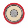

(N)TMCGCW11Y Cable – Screened MV Crane Cable
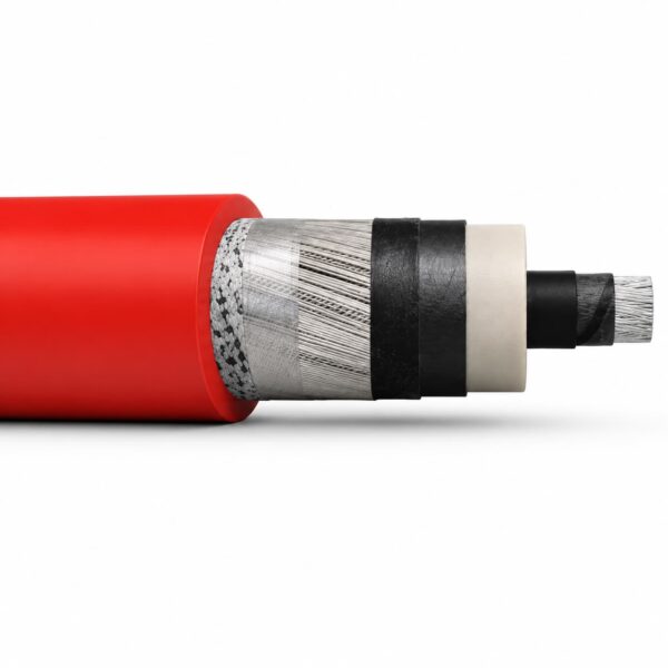
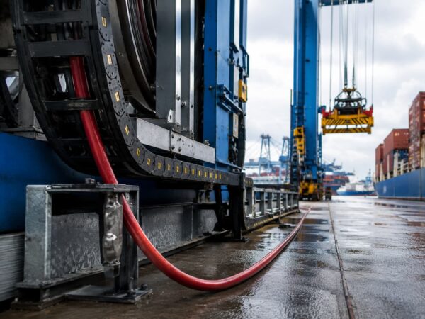
(N)TMCGCW11Y cable is a screened, flexible single-core medium-voltage cable for crane energy chains, shore-power equipment, cable carriers, and short switchgear or transformer links. Its Class 5 tinned-copper conductor, EPR insulation system, concentric protective conductor, and red TPU/PUR outer sheath support compact routing and demanding movement where a standard fixed MV cable is not suitable.
What is (N)TMCGCW11Y cable?
(N)TMCGCW11Y cable is a screened, flexible single-core medium-voltage cable for short power links and controlled movement. It combines a Class 5 tinned-copper conductor, EPR insulation with semiconductive stress-control layers, a concentric protective conductor, and a mechanically resistant red TPU/PUR outer sheath.
The construction is intended for applications where voltage is only part of the decision. The route may also impose repeated bending, carrier contact, oil, moisture, outdoor exposure, or limited termination space. That makes the cable relevant to crane energy chains, shore-power systems, large drives, and compact switchgear or transformer connections.
It is not a general-purpose building cable, and its flexibility does not make it suitable for every reeling or trailing duty. Confirm the complete movement pattern, minimum bend radius, tensile load, carrier geometry, terminations, and applicable standard before ordering.
A screened single-core MV crane cable controls electrical stress while keeping each phase cable flexible and manageable. The semiconductive layers form the insulation-screen interface, while the concentric tinned-copper conductor supports the defined protective-earth arrangement. The final system still depends on correct bonding, accessories, and termination workmanship.
Project reference: this cable type is used for a medium voltage power connection in a data center in Singapore.
How is (N)TMCGCW11Y cable constructed?
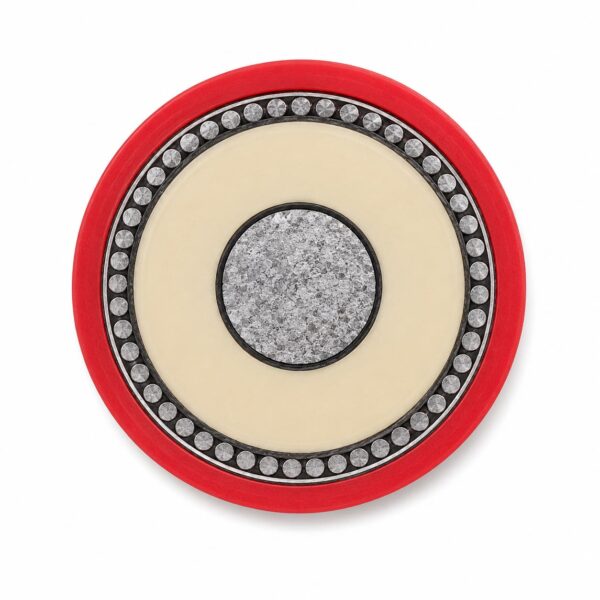
The cable uses a layered screened single-core construction for flexible medium-voltage service. A Class 5 tinned-copper conductor sits beneath semiconductive stress-control layers and EPR insulation. Concentric tinned-copper strands provide the protective-conductor layer, and a red thermoplastic polyether-based TPU/PUR sheath protects the assembly.| Element | Construction detail | Why it matters |
|---|---|---|
| Conductor | Tinned copper wires, finely stranded, Class 5 according to DIN EN/IEC 60228 | Supports flexibility in short MV links and controlled moving routes. |
| Inner stress-control layer | Inner semiconductive layer over the conductor | Creates a controlled electrical interface between the stranded conductor and insulation. |
| Insulation | EPR compound with improved electrical and mechanical characteristics, based on DIN VDE 0207-20 | Provides the main dielectric layer while retaining flexibility for the stated duty. |
| Outer insulation screen | Outer semiconductive insulation shield | Completes the controlled screen interface around the insulated conductor. |
| Protective conductor | Concentric tinned-copper strands based on DIN VDE 0250-1, approximately 85% coverage | Supports the specified protective-earth and screening arrangement; final bonding and fault duty require project review. |
| Outer sheath | Red thermoplastic polyether-based polyurethane according to EN 50363-10-2 | Provides the stated mechanical, oil, UV, ozone, moisture, and outdoor-resistance profile. |
Which applications suit (N)TMCGCW11Y cable?
(N)TMCGCW11Y suits short flexible MV links and controlled moving systems that match its published bend, speed, tension, and environmental limits. Common routes include port-crane energy chains, shore-power handling systems, large drives, compact switchgear links, transformer houses, and selected industrial or mining equipment.| Application | Relevant published feature | Project inputs required |
|---|---|---|
| Port or intermodal crane energy chain | Free-moving radius ≥ 8 × OD; stated speed range 70–240 m/min | Chain radius, travel, acceleration, cycles, tensile load, alignment, and abrasion points |
| Shore-power cable management | Stated shore-power movement reference of 6 m/min; outdoor and moisture resistance references | Reel/carrier geometry, connector system, water pressure, vessel interface, and grounding |
| Switchgear or transformer link | Fixed radius ≥ 6 × OD and screened single-core MV construction | Voltage, fault duty, phase spacing, bonding, glands, and termination clearances |
| Large drive or industrial carrier | Class 5 conductor and mechanically resistant TPU/PUR sheath | Carrier design, movement frequency, oil/chemical exposure, temperature, and route length |
| Mining equipment route | Low-temperature, oil, moisture, abrasion, and screened MV references | Confirm whether the duty is carrier, trailing, reeling, or fixed; do not infer interchangeability from environment alone |
When should another cable family be reviewed?
- Review a purpose-built multi-core reeling cable when all phases must cycle together on a drum.
- Use a low-voltage festoon cable for 0.6/1 kV festoon or trolley systems.
- Compare a fixed MV distribution cable when the route has no dynamic movement.
- Choose a trailing cable designed for ground contact when dragging, crushing, or vehicle crossings define the duty.
What are the main (N)TMCGCW11Y cable specifications?
The product range covers 3.6/6 kV through 18/30 kV with Class 5 tinned-copper conductors and a red TPU/PUR sheath. Published mechanical references include 6 × OD fixed and 8 × OD free-moving bend radii, 15 N/mm² tensile load per conductor, and flexible operation from -40 °C to +90 °C.| Product type | Flexible medium-voltage screened single-core crane and shore-power cable |
|---|---|
| Model | (N)TMCGCW11Y |
| Rated voltage U0/U | 3.6/6, 6/10, 8.7/15, 12/20, 14/25, and 18/30 kV |
| Conductor | Class 5 finely stranded tinned copper |
| Insulation | EPR compound with inner and outer semiconductive stress-control layers |
| Protective conductor | Concentric tinned-copper ground conductor, approximately 85% coverage |
| Outer sheath | Red thermoplastic polyether-based polyurethane; supplied data references halogen-free, flame, oil, UV, ozone, and moisture performance |
| Fixed temperature range | -50 °C to +90 °C |
| Flexible temperature range | -40 °C to +90 °C |
| Maximum conductor temperature | 90 °C |
| Maximum short-circuit temperature | 200 °C |
| Maximum tensile load | 15 N/mm² per conductor |
| Minimum bend radius, fixed | 6 × overall diameter |
| Minimum bend radius, free moving | 8 × overall diameter |
| Published movement references | Shore power: 6 m/min; crane energy chains: 70–240 m/min |
Voltage and test parameters
| Parameter | 3.6/6 kV | 6/10 kV | 8.7/15 kV | 12/20 kV | 14/25 kV | 18/30 kV |
|---|---|---|---|---|---|---|
| Maximum AC operating voltage Umax | 4.2/7.2 kV | 6.9/12 kV | 10.4/18 kV | 13.9/24 kV | 17.3/30 kV | 20.8/36 kV |
| Maximum DC operating voltage Umax | 5.4/10.8 kV | 9/18 kV | 13.5/27 kV | 18/36 kV | 22.5/45 kV | 27/54 kV |
| AC test voltage, DIN VDE 0250-813 reference | 11 kV | 17 kV | 24 kV | 29 kV | 36 kV | 43 kV |
| Derating | Apply the installation-specific factors required by DIN VDE 0298-4 or the governing project method. | |||||
Dimensions, weight, resistance, and current data
Use these tables for first-stage conductor sizing, gland and termination planning, carrier clearance, approximate cable weight, and current review. Current capacity depends on the stated reference conditions and applicable derating; validate the final cable drawing and installation calculation before ordering.3.6/6 kV
| Size (mm²) | Max. conductor resistance (Ω/km) | Diameter over insulation (mm) | Overall diameter (mm) | Calculated weight (kg/km) | Current reference (A) |
|---|---|---|---|---|---|
| 1 × 25/16 | 0.795 | 13.0 | 20–23 | 730 | 135 |
| 1 × 35/16 | 0.565 | 14.5 | 22–25 | 845 | 169 |
6/10 kV
| Size (mm²) | Max. conductor resistance (Ω/km) | Diameter over insulation (mm) | Overall diameter (mm) | Calculated weight (kg/km) | Current reference (A) |
|---|---|---|---|---|---|
| 1 × 25/16 | 0.795 | 13.0 | 20–23 | 730 | 135 |
| 1 × 35/16 | 0.565 | 14.5 | 21–24 | 860 | 169 |
| 1 × 50/16 | 0.393 | 16.0 | 23–26 | 1,045 | 207 |
| 1 × 70/16 | 0.277 | 18.0 | 25–28 | 1,285 | 268 |
| 1 × 95/16 | 0.210 | 19.0 | 26–29 | 1,540 | 328 |
| 1 × 120/16 | 0.164 | 21.0 | 28–31 | 1,805 | 383 |
| 1 × 150/25 | 0.132 | 23.0 | 30–33 | 2,160 | 444 |
| 1 × 185/25 | 0.108 | 25.0 | 32–35 | 2,505 | 510 |
| 1 × 240/25 | 0.0817 | 27.0 | 35–38 | 3,080 | 607 |
| 1 × 300/25* | 0.0654 | 29.0 | 37–40 | 3,705 | 703 |
12/20 kV
| Size (mm²) | Max. conductor resistance (Ω/km) | Diameter over insulation (mm) | Overall diameter (mm) | Calculated weight (kg/km) | Current reference (A) |
|---|---|---|---|---|---|
| 1 × 25/16 | 0.795 | 17.0 | 24–27 | 925 | 135 |
| 1 × 35/16 | 0.565 | 18.0 | 25–28 | 1,060 | 169 |
| 1 × 50/16 | 0.393 | 19.0 | 26–29 | 1,250 | 207 |
| 1 × 70/16 | 0.277 | 21.0 | 28–31 | 1,515 | 268 |
| 1 × 95/16 | 0.210 | 23.0 | 30–33 | 1,785 | 328 |
| 1 × 120/16 | 0.164 | 24.0 | 32–35 | 2,060 | 383 |
| 1 × 150/25 | 0.132 | 26.0 | 35–38 | 2,450 | 444 |
| 1 × 185/25 | 0.108 | 28.0 | 36–39 | 2,808 | 510 |
| 1 × 240/25 | 0.0817 | 30.0 | 38–41 | 3,340 | 607 |
18/30 kV
| Size (mm²) | Max. conductor resistance (Ω/km) | Diameter over insulation (mm) | Overall diameter (mm) | Calculated weight (kg/km) | Current reference (A) |
|---|---|---|---|---|---|
| 1 × 25/16 | 0.795 | 20.0 | 27–30 | 1,130 | 135 |
| 1 × 35/16 | 0.565 | 21.5 | 29–32 | 1,300 | 169 |
| 1 × 50/16 | 0.393 | 23.0 | 30–33 | 1,500 | 207 |
| 1 × 70/16 | 0.277 | 25.0 | 32–35 | 1,750 | 268 |
| 1 × 95/16 | 0.210 | 26.0 | 34–37 | 2,075 | 328 |
| 1 × 120/25 | 0.164 | 28.0 | 36–39 | 2,350 | 383 |
| 1 × 150/25 | 0.132 | 30.0 | 38–41 | 2,725 | 444 |
| 1 × 185/25 | 0.108 | 32.0 | 40–43 | 3,100 | 510 |
| 1 × 240/25 | 0.0817 | 34.0 | 42–45 | 3,640 | 607 |
Standards and test references
The references below come from the supplied technical data. They describe construction or test methods; they are not presented as third-party product certificates. Confirm the required edition, regional adoption, project specification, and documentary evidence before approval.| Topic | Published reference | Verification note |
|---|---|---|
| Cable construction basis | DIN VDE 0250-813 | Confirm the project-required edition and product documentation. |
| Flexible conductor | IEC 60228, Class 5 conductor requirements | The IEC publication covers conductor construction and resistance requirements; it does not approve the complete cable application. |
| EPR insulation material basis | DIN VDE 0207-20 | Confirm compound and test documentation for the ordered construction. |
| Protective conductor | DIN VDE 0250-1 | Check protective-conductor size, fault duty, bonding, and termination design. |
| TPU/PUR sheath material | EN 50363-10-2 | Material designation alone does not establish suitability for every chemical or mechanical exposure. |
| Single-cable flame test | IEC 60332-1-2 vertical flame-propagation test | A single-cable test is not the same as installed bunch-fire performance. |
| Oil-resistance test | IEC 60811-404 mineral-oil immersion test | Compare the actual fluid, temperature, duration, and acceptance criteria with the test scope. |
| Halogen acid gas test | IEC 60754-1 halogen acid gas test | This method tests material components and does not replace the complete project fire assessment. |
| Water exposure | Protection class AD8 according to supplied data, at pressure ≤ 10 bar | Confirm water type, pressure, duration, accessories, terminations, and the project evidence required. |
Request a cable recommendation and quotation
Send the required services, cable length, mechanical duty, environment, termination and quantity. Our team will review the application before quoting.
- Include the product name or SKU plus the required cable length and quantity.
- Attach a specification, drawing or data sheet when available.