

NEK 606 BFOU Cable | P5/P12 Power & Instrumentation
NEK 606 BFOU cable family: P5/P12 0.6/1 kV offshore power reference, BFOU(c) 150/250 V HFFR EPR/EVA instrumentation and BFOU(i) 250 V fire-resistant instrumentation. Fixed marine/offshore installation; confirm P-code, screen, fire test and size at RFQ.
NEK 606 BFOU cable for fixed offshore power, lighting, control and instrumentation, with the current page retained for the BFOU P105 0.6/1 kV reference. This page now groups the requested BFOU family terms: P5/P12 offshore power, BFOU(c) 150/250 V HFFR EPR/EVA instrumentation and BFOU(i) 250 V fire-resistant instrumentation.
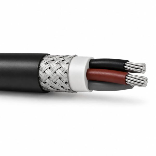
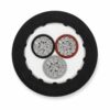
BFOU power builds use a fire-resistant insulation system and metallic braid for fixed routes where the project requires circuit integrity and mechanical protection. BFOU(c) is the collectively screened instrumentation/control form; BFOU(i) is the individually screened instrumentation form. Pair/triple count, screen design, sheath compound, colour, core identification and fire test duration must be taken from the ordered datasheet. The P105 product data currently lists tinned copper, mica plus halogen-free EPR, TCWB braid and black SHF2 H-M sheath.
Use this page for engineering selection and RFQ preparation, not as a substitute for a project approval schedule. Send voltage, P-code, core or pair/triple count, conductor area, route, bending requirement, temperature, fire-integrity duration, mud/oil exposure and any classification documentation required. Compare the related NEK 606 RFOU range, NEK 606 UX earth cable and the Marine & Offshore Cables category before ordering.
Construction
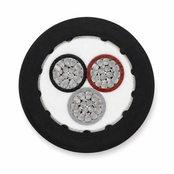
The current P105 reference uses a fire-resistant mica tape plus halogen-free EPR insulation system, fibreglass bedding/fillers, SHF2 inner sheath, tinned copper wire braid (TCWB) and black SHF2 H-M outer sheath. Instrumentation variants use the same NEK 606 design logic but add individual or collective screening according to the code.
| Variant | Construction focus | Selection check |
|---|---|---|
| BFOU P5/P12 power (P105 page reference) | Tinned copper; mica tape + halogen-free EPR; fibreglass bedding/fillers; SHF2 inner sheath; TCWB; black SHF2 H-M or mud-resistant outer sheath. | Confirm P-code, core count, conductor class and fire-test scope. |
| BFOU(c) | 150/250 V instrumentation/control cable with EPR insulation, HFFR/EVA or SHF2-type sheath, collective screen and TCWB braid. | Confirm pair/triple count, collective screen/drain and sheath colour. |
| BFOU(i) | 250 V instrumentation cable with individually screened pairs/triples, mica/EPR fire-resistant layer, TCWB braid and halogen-free SHF2 sheath. | Confirm individual screens, fire-integrity duration and intrinsically safe colour if required. |
Applications
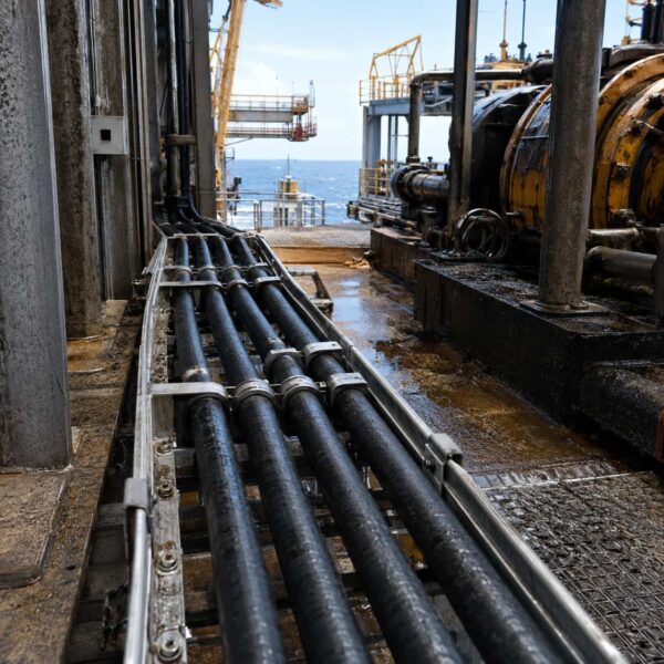
- Fixed 0.6/1 kV offshore power distribution, lighting and control routes.
- Emergency and critical circuits where the project specifies a fire-resistant BFOU construction.
- BFOU(c) instrumentation, communication, control and alarm systems with collective screening.
- BFOU(i) individually screened instrumentation and communication circuits in safe or hazardous-area designs, subject to the project approval schedule.
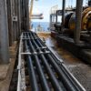
- Marine and offshore cable trays, modules and drilling-unit routes exposed to mud, oil, saline atmosphere or cleaning fluids when the ordered sheath code covers the exposure.
Installation boundary: fixed installation only unless a separate engineering review approves another duty. Confirm glands, braid bonding, EMC, earthing, minimum bend radius and fire-integrity requirements before installation.
Specifications
The P105 values below are the current product reference. BFOU(c) and BFOU(i) values identify the requested family variants; final dimensions and electrical data depend on pair/triple or core size.
| Selection | Voltage / temperature | Key data |
|---|---|---|
| BFOU P5/P12 power; P105 page reference | 0.6/1 kV Uo/U; 1.2 kV maximum operating voltage; +90°C maximum conductor temperature. | Fixed installation; 1-4 core options are listed on the current page; minimum bending radius 4 x overall diameter; black sheath. |
| BFOU(c) instrumentation | 150/250 V (project notation may show 250 V); max. conductor temperature commonly +90°C. | Collectively screened pairs/triples; EPR insulation; HFFR/EVA or SHF2-type sheath; confirm size, screen and bend radius. |
| BFOU(i) instrumentation | 250 V; max. conductor temperature commonly +90°C. | Individually screened pairs/triples; fire-resistant mica/EPR system; confirm fire test duration, core identification and sheath colour. |
RFQ data: include core/pair/triple count, nominal area, conductor class, screen type, overall diameter, weight, capacitance/inductance, current or signal limits and termination details. Do not size accessories from a family name alone.
Standards
The requested BFOU designations are used within the NEK 606 offshore cable family. State the edition, code and required test duration in the project specification.
| Reference | Use on this page |
|---|---|
| NEK 606 / NEK TS 606 | P5/P12 power and BFOU(c)/BFOU(i) offshore designations, including mud/oil service requirements where specified. |
| IEC 60092-353, IEC 60092-376, IEC 60092-360 | Power, instrumentation and shipboard insulation/sheath design references. |
| IEC 60331-1/-2/-21 | Fire-resistance / circuit-integrity test references for the ordered BFOU construction. |
| IEC 60332-1-2 and IEC 60332-3-22 | Flame-retardant and bunched-cable flame-spread references. |
| IEC 60754-1/2 and IEC 61034-1/2 | Halogen-gas/corrosivity and smoke-density test references. |
| IEC 60228 | Conductor class and resistance reference. |
Request the model-specific certificate, classification approval and test report required by the project; a standards reference alone is not an approval claim.
Related cable options
Compare these cable options by service combination, movement, load, voltage and transmission requirement.
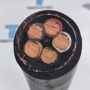
5G 35mm2 RFOU Cable | NEK 606 Power & Instrumentation
A related cable option for a different application or duty profile.
View product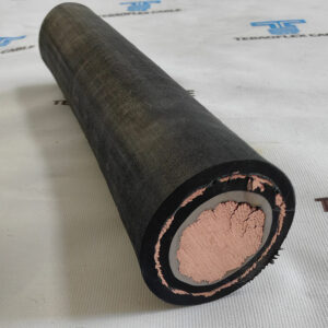
0.6/1kV RFOU Cable for Marine & Offshore NEK 606 Projects
A related cable option for a different application or duty profile.
View product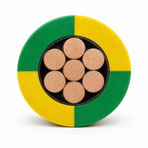
NEK 606 P108 UX 0.6/1kV Offshore Earth Cable
A related cable option for a different application or duty profile.
View productRequest a cable recommendation and quotation
Send the required services, cable length, mechanical duty, environment, termination and quantity. Our team will review the application before quoting.
- Include the product name or SKU plus the required cable length and quantity.
- Attach a specification, drawing or data sheet when available.