

Subsea equipment, tow systems and marine instruments
Custom Subsea & Marine Cable Manufacturer
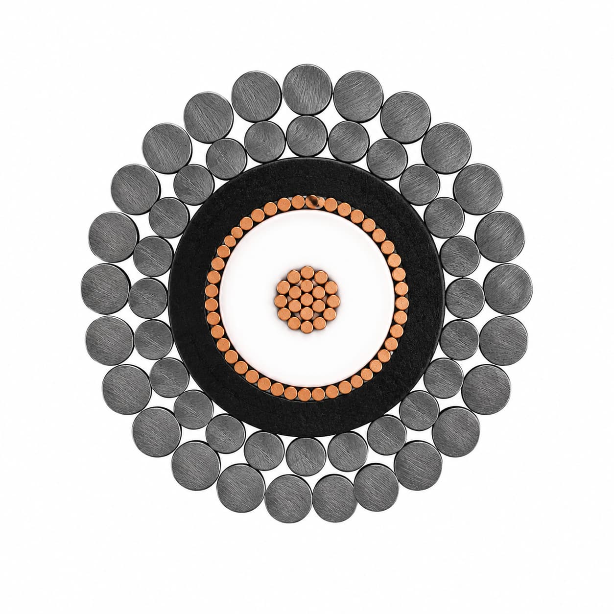
TEBAOFLEX develops application-specific cable constructions that combine power, signal, coaxial or optical elements with mechanical reinforcement for underwater equipment and deployment systems.
- Power, signal, coaxial and fibre
- Static, suspended, reeled or towed
- Cable and termination reviewed together
Choose by system duty, not by name alone
Use this page to narrow the cable route before comparing a product model or submitting a specification.
Start with the equipment
Identify the machine, circuit function, route and the consequence of cable failure at that location.
Define the complete duty
State voltage or transmission needs together with movement, bending, load, fluids, temperature and installation exposure.
Confirm one construction
Review conductor or fibre elements, screens, reinforcement, sheath, termination, standards and documentation as one schedule.
Match the cable to the equipment and route
Start with the equipment mission and deployment method, then choose the cable family that carries the required services and mechanical duty.
ROV and AUV systems
Power, control, video, Ethernet or fibre services matched to tether handling, vehicle interface and termination constraints.
View a compact power-and-fibre routeTowed sonar and arrays
Load-bearing coaxial, paired-signal or hybrid routes for sonar bodies, hydrophones and marine survey equipment.
View a coaxial tow-cable routeOceanographic instruments
Winch-deployed cables for CTD systems, cameras, sensors, samplers and research-vessel equipment.
View an instrumentation routeUnderwater video and telemetry
Coaxial transmission, power, control cores or screened pairs combined where separate cables complicate deployment and termination.
View a hybrid coaxial routeOptical monitoring and sensing
Load-bearing fibre for high-bandwidth underwater links that do not need copper power conductors.
View a pure optical routeDeepwater hybrid systems
Electro-optical and mechanically reinforced routes reviewed around load, handling, waterblocking and termination.
View a deepwater high-load routeDefine the conditions that control cable life
The costly failure is rarely described by the product name. Separate signal compatibility, movement, environment and interface risks before choosing a construction.
A nominal cable type is not enough. Define coaxial impedance and frequency, allowable attenuation, or fibre type, count and wavelength together with cable length.
A static underwater cable can fail on a winch. State whether the route is suspended, reeled, towed or repeatedly deployed, with load and bend geometry.
Temperature, water migration, hydrolysis, abrasion, chemicals and corrosion determine which insulation, sheath, waterblocking and armour route is credible.
Diameter, bend radius, armour anchoring, sealing, moulding and available equipment space can eliminate an otherwise suitable electrical or optical design.
Compare suitable cable-family routes
Use the limiting engineering problem to choose a family first. The product routes below then separate impedance, circuit count, temperature, optical power integration and load capacity.
Impedance plus towing load
For a single 39-45 Ohm or 50 Ohm coaxial path that must also carry deployment load. Match the equipment interface before comparing diameter and strength.
Start with 39-45 Ohm coaxial routesHeat, sensor circuits and compact envelopes
For elevated-temperature conductors or compact underwater sensing and control circuits where material, core count and handling duty are the limiting choices.
Start with instrumentation routesCoax, power and control in one interface
For sonar, video or telemetry systems that need coaxial transmission plus electrical services without separate tow-cable terminations.
View hybrid coaxial constructionsOptical data, with or without power
Choose pure optical cable when copper power is unnecessary, compact electro-optical cable when space controls, or a high-load route for demanding deployment duty.
Start with the pure optical routeTurn the application into a cable selection route
Use the matrix to identify the next technical route. Final construction follows the complete project schedule and operating inputs.
| Equipment or Route | Cable System | Inputs to Confirm | Selection Route |
|---|---|---|---|
| 39-45 Ohm sonar or telemetry | Single-coax armoured tow cable | Impedance, frequency, attenuation, length, load, drum, sheave and termination | 39-45 Ohm coaxial route |
| 50 Ohm RF, video or telemetry | 50 Ohm high-voltage coaxial tow cable | Verified 50 Ohm interface, voltage, attenuation, length and mechanical duty | 50 Ohm coaxial route |
| Elevated-temperature instrument | Single-core or multicore armoured cable | Operating temperature, circuit count, material system, bending, load and termination | High-temperature route |
| Sensor, camera or control circuit | Compact or multicore instrumentation cable | Circuit count, corrosion, water, handling mode, diameter and connector envelope | Instrumentation route |
| Towed system with coax plus power | Hybrid coaxial power and signal cable | Coax count and impedance, power, screened pairs, heat, load and termination | Hybrid coaxial route |
| Optical-only underwater link | Armoured fibre optic cable | Fibre type and count, wavelength, attenuation, load, bend and connector | Pure optical route |
| Compact ROV power and fibre | Compact electro-optical cable | Power cores, fibre count, diameter, bend geometry, load and vehicle interface | Compact hybrid route |
| Deepwater multi-service equipment | High-load electro-optical cable | Power, signals, fibre, working load, depth, waterblocking, armour and termination | Deepwater high-load route |
Engineering and test references
References are selected for the confirmed construction and project duty. The quotation and inspection plan define the applicable methods, conditions and acceptance values.
Reference 1
IEC 61196-1 provides a design and electrical test-method framework where coaxial communication elements are included.
Reference 2
IEC 60794-1-2 and related mechanical and environmental test families are reviewed where optical or hybrid optical elements are included.
Reference 3
IEC 60228 is used as a conductor resistance and conductor-class reference for separately specified insulated copper cores.
Reference 4
The project inspection plan defines the applicable electrical, optical, mechanical, environmental and completed-cable acceptance methods.
From operating data to an agreed cable schedule
The process keeps equipment, cable construction, interfaces and documentation aligned before production.
Share the operating duty
Provide the equipment, electrical or transmission services, movement, route and environment.
Review the cable route
Separate circuit functions and compare the constructions that fit the operating duty.
Confirm the technical schedule
Agree the construction, dimensions, interfaces, standards, inspection stages and document list.
Manufacture and inspect
Production, marking, packing and agreed inspection follow the confirmed order specification.
Frequently asked questions
Short answers to common questions before a project-specific cable review.
What is the difference between a subsea equipment cable and a submarine infrastructure cable?
This page addresses cables for equipment, instruments, towing, deployment and compact power or data systems. Long-distance submarine power and telecommunications infrastructure has different installation, jointing and system requirements.
When should a subsea equipment cable be armoured?
Armour is considered when the cable must carry deployment or towing load, needs mechanical protection, or must transfer load into a termination. Armour material, lay, corrosion exposure, bending and anchoring must be reviewed together.
Can power, coaxial signal and fibre be combined?
Yes, a hybrid construction can combine services when the electrical, optical, screening, heat, diameter, load and termination requirements are engineered as one cable system.
Can a static underwater cable be used on a winch?
Not without confirming the dynamic duty. Reeling introduces repeated bending, drum pressure, tension, layer interaction and handling conditions that a static construction may not be designed to withstand.
Send the inputs needed for a useful cable review
Include the information available now. Drawings, old cable markings, cross-section photos and project specifications can be attached through the enquiry form.
- Equipment, application and mission
- Fresh water or sea water and operating depth when relevant
- Static, suspended, towing, reeling or tether-management duty
- Cable length, quantity, voltage, current and power
- Signal protocol, frequency, screening or coaxial impedance
- Fibre type, count, wavelengths and attenuation requirement
- Working-load and breaking-load criteria
- Winch drum, sheave, routing and deployment cycle
- Temperature, abrasion, chemicals, corrosion, waterblocking and buoyancy target
- Connector, moulding, armour termination and required inspection documents