

High Voltage Igniter Wire 25 kV, 250°C and 538°C
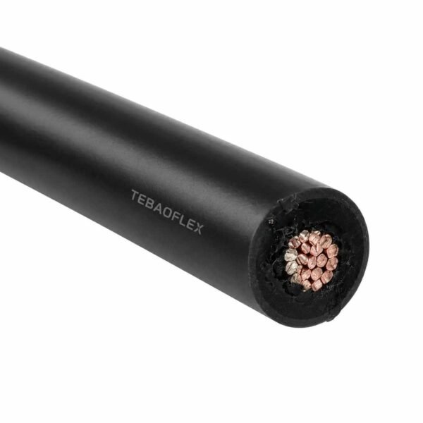
25 kV igniter wire in two builds — 538 °C mica/fiberglass and 250 °C fluoropolymer. Unscreened single core, made to run length.
- Rating: 25 kV DC / 17 kV AC, both builds
- 538 °C build: multi-layer mica tape + moisture barrier under impregnated fiberglass braid
- 250 °C build: extruded fluoropolymer, UL AWM Style 1911
- Conductor: finely stranded nickel-plated copper, 18 AWG standard
- Typical OD: 8.6 mm (538 °C) / 2.49 mm (250 °C)
- Bend radius: 6 × OD static (538 °C) / 12 × OD static (250 °C)
- Screen: none — unscreened by design
Send the conductor temperature at the rod, the transformer output and the run length for a quotation.
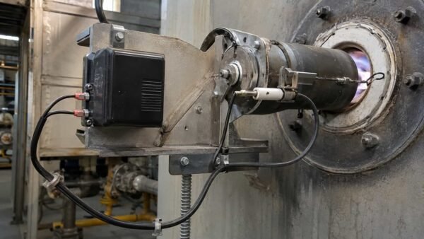
Igniter wire is the lead between the ignition transformer or exciter and the spark rod, and it lives in the worst place in the combustion chamber’s neighbourhood. TEBAOFLEX builds it at 25 kV DC / 17 kV AC in two constructions that share the voltage class and nothing else:
A mica and fiberglass build rated 538 °C (1,000 °F), where the insulation is inorganic because no polymer survives up there — multi-layer mica tape with a moisture barrier under an impregnated fiberglass braid. And a fluoropolymer build rated 250 °C in UL AWM Style 1911, which trades the top of the temperature range for a wire less than a third the diameter and far better resistance to oil, solvent and abrasion.
Both use finely stranded nickel-plated copper, both are unscreened single cores, and both are made to the run length between your transformer and your rod. Which one you need is decided by one number: the temperature the conductor actually reaches at the terminal end — not the room temperature, and not the flame temperature.
These sit a full class above the 7–10 kV engine and burner leads elsewhere in our range, and above flare stack ignition cable, which is 25 kV DC but only 10 kV AC and 250 °C. For the full material and temperature picture, see the high temperature wire selection matrix and the rest of the high temperature cable range.
Send the conductor temperature at the rod, the transformer output and the run length, and we will tell you which of the two you should be buying — including when the answer is the cheaper one.
Two builds, one voltage class. The conductor and the job are identical; the insulation system is where they part company, and that choice sets the diameter, the stiffness and the price.
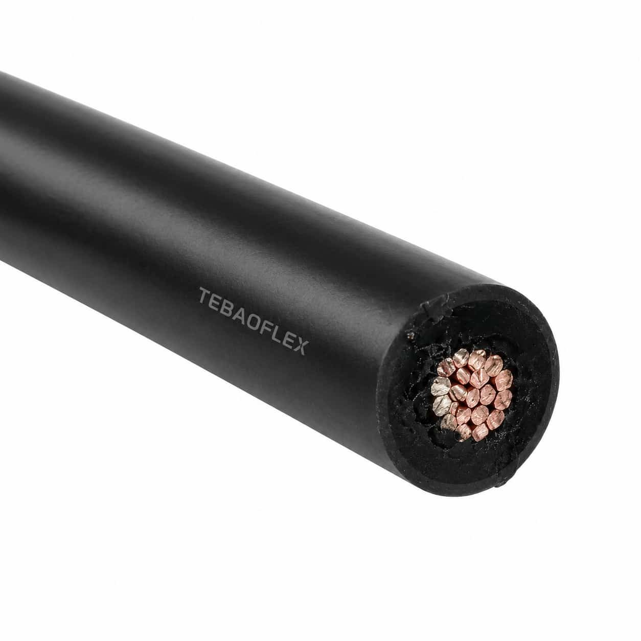
The 538 °C build: mica and glass
- Conductor: finely stranded nickel-plated copper, 18 AWG standard. Nickel is not a preference at this temperature, it is the only common plating that survives it.
- Insulation: multi-layered mica tape, helically wrapped. Mica is a mineral, not a polymer — that is the entire point. At 538 °C there is no plastic left to melt because there was never any plastic doing the insulating.
- Moisture barrier: a thin PTFE barrier in the wrap. Mica’s one weakness is that it will take up moisture, and wet mica is not an insulator. The barrier protects the wrap during storage, installation and washdown.
- Jacket: an impregnated fiberglass braid, finished so it does not fray when it is cut and terminated.
The 250 °C build: fluoropolymer, UL AWM Style 1911
- Conductor: the same finely stranded nickel-plated copper.
- Insulation: extruded fluoropolymer, which is both the dielectric and the jacket. One layer does everything.
That is the whole construction, and it is why this version is a fraction of the diameter. It also carries a UL AWM style number, which the mica build cannot, because no AWM style describes a mica-and-glass high-voltage construction.
Why the hot one is fatter and the cool one is thinner
Mica tape has to be wrapped, not extruded, and a wrapped dielectric needs many more turns to reach the same withstand than an extruded one needs millimetres. Add the glass braid and the 538 °C build lands at roughly 8.6 mm over an 18 AWG conductor. The fluoropolymer version reaches the same 25 kV DC in 2.49 mm. Same conductor, same voltage, three and a half times the diameter — and every bit of that difference is the price of the extra 288 °C.
Bend radius: multiply it out before you compare
The 538 °C build is specified at 6 × OD static, 8 × OD dynamic. The fluoropolymer build is 12 × OD static, 15 × OD dynamic. Read as multipliers, the hot one looks twice as flexible. It is not. Multiply them out: 6 × 8.6 mm is a 52 mm static radius; 12 × 2.49 mm is 30 mm. The thin wire still turns the tighter corner by a wide margin. Bend radius multipliers only compare within one construction — across constructions they are actively misleading, and this is the pair that catches people out.
No screen, and that is deliberate
Neither build has a metallic screen or a drain wire. On a 25 kV ignition circuit a screen is somewhere for the discharge to go that is not the rod. The fiberglass braid on the hot build is mechanical and thermal; do not bond it and do not terminate it as a shield.
Igniter wire has one duty and it is unforgiving: deliver a spark to a rod that is sitting next to, or inside, a flame. Everything on this page follows from the temperature the conductor reaches at that end.
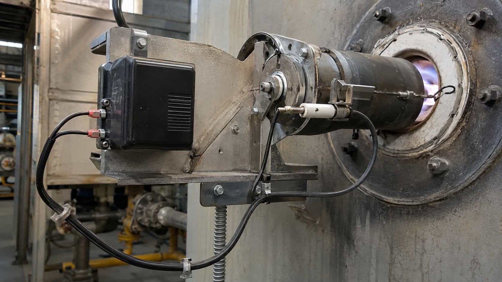
Where it is used
- Industrial burner igniters — process heaters, reformers, kilns and furnaces using spark-rod ignition.
- Boiler and package boiler ignition — gas and oil-fired, including retractable igniter assemblies.
- Gas turbine and engine test cell igniters — short runs, high cycle count, high ambient.
- Incinerator and thermal oxidiser igniters — the classic case for the 538 °C build.
- Flare pilots — where the igniter sits at the tip rather than at grade. For the long run up the stack, see flare stack ignition cable.
- High-energy ignition (HEI) systems — capacitive-discharge exciters feeding a surface-gap or air-gap igniter.
Which of the two builds you need
This is the only decision on this page that matters, and it turns on the conductor temperature at the terminal end — not the ambient in the burner house, and certainly not the flame temperature.
| If the conductor at the rod sees… | Buy | Because |
|---|---|---|
| Up to 250 °C | Fluoropolymer, UL AWM 1911 | A quarter of the diameter, tighter real bend radius, better oil and solvent resistance, a listed style number, and cheaper |
| 250 °C to 538 °C | Mica / fiberglass | No polymer dielectric survives above roughly 260 °C continuously; the insulation has to be inorganic |
| You do not know | Measure before you buy | Buying the 538 °C build “to be safe” means four times the diameter, a stiffer route and a bigger gland for a margin you may not need |
Over-specifying here is not free. The mica build is bulkier, stiffer and dearer, and on a tight igniter assembly the extra diameter can be the reason it does not fit the conduit you already have.
Where igniter wire fails
- At the splice, every time. A field splice on a 25 kV lead is a manufactured weak point — the discharge will find it before it finds the rod. Order the run length and terminate at both ends properly; do not join two offcuts.
- At the terminal end, from heat you did not budget for. The rod conducts heat back into the lead. If the last 300 mm is discoloured or the braid has gone brittle, the conductor temperature is above what you specified.
- From moisture in the mica. Wet mica stops insulating. Keep the reel sealed, cut only what you need, and terminate the cut end the same day.
- From a bend that cracked the wrap. On the mica build a kink can fracture the wrap without marking the braid. It will pass a visual check and fail months later as an intermittent misfire.
- From treating the braid as a screen. Bonding the fiberglass braid does nothing electrically and can mislead the next technician into thinking the circuit is screened.
What this wire is not for
- Not an engine or small-burner lead. At 7–10 kV use 7–10 kV silicone ignition cable or Style 3304 / 3573 10 kV ignition wire. Paying for 25 kV and 538 °C on a genset lead is money spent on nothing.
- Not equipment internal HV wiring. For leads inside a cabinet or an imaging or test set, use high voltage silicone wire in UL 3239 or UL 10475.
- Not a general 538 °C hook-up wire. Mica-glass hook-up wire at 300–600 V is a different, much thinner product; do not buy a 25 kV lead to wire a furnace terminal box.
- Not a screened HV cable. No screen, no drain wire, by design.
- Not a thermocouple or flame-rod lead. Flame proving is a separate circuit with its own cable.
Hot-zone equipment leads at 300 V need a different construction from this igniter wire, such as the UL 5390 mica-glass wire rated 550°C and 300 V AC for internal equipment wiring.
The two builds side by side
| Property | Mica / fiberglass build | Fluoropolymer build |
|---|---|---|
| Max conductor temperature | 538 °C (1,000 °F) | 250 °C (482 °F) |
| Voltage rating | 25 kV DC / 17 kV AC | 25 kV DC / 17 kV AC |
| UL AWM style | None — factory-rated construction | Style 1911 |
| Conductor | Finely stranded nickel-plated copper | Finely stranded nickel-plated copper |
| Standard size | 18 AWG (16/30 stranding) | 18 AWG (19-strand) |
| Insulation | Multi-layer mica tape with moisture barrier | Extruded fluoropolymer |
| Jacket | Impregnated fiberglass braid | The fluoropolymer is the jacket |
| Screen | None | None |
| Typical OD | 8.6 mm (0.339 in) | 2.49 mm (0.098 in) |
| Typical weight | 75 kg/km | 16 kg/km |
| Bend radius, static | 6 × OD (about 52 mm) | 12 × OD (about 30 mm) |
| Bend radius, dynamic | 8 × OD (about 69 mm) | 15 × OD (about 37 mm) |
| Resists | Heat, flexing | Heat, flexing, chemicals, abrasion |
Fluoropolymer build — sizes and voltage classes
The UL AWM 1911 construction is the one that scales, because the wall is extruded and can simply be made thicker for a higher class. Typical finished dimensions:
| Class | AWG | Strands | Typical OD (mm) | Typical OD (in) | Typical weight (kg/km) |
|---|---|---|---|---|---|
| 10 kV DC | 24 | 7 | 1.56 | 0.062 | 5.7 |
| 10 kV DC | 22 | 7 | 1.73 | 0.068 | 7.5 |
| 10 kV DC | 20 | 7 | 1.90 | 0.075 | 9.6 |
| 10 kV DC | 18 | 19 | 2.08 | 0.082 | 12.6 |
| 25 kV DC | 20 | 7 | 2.30 | 0.091 | 12.5 |
| 25 kV DC | 18 | 19 | 2.49 | 0.098 | 15.9 |
| 30 kV DC | 20 | 7 | 2.51 | 0.099 | 14.2 |
| 30 kV DC | 18 | 19 | 2.69 | 0.106 | 17.7 |
Read the table down a column, not across. An 18 AWG conductor appears at 10, 25 and 30 kV and it is the same conductor every time — 2.08, 2.49 and 2.69 mm of finished diameter is the wall growing, not the copper. Current sizes the conductor; voltage sizes the wall. Going up two kV classes on the same 18 AWG costs 0.6 mm of diameter and about 5 kg/km, and that is the entire difference.
Mica / fiberglass build — sizes
18 AWG at 8.6 mm is the standard offering and covers the great majority of igniter duty. Other conductor sizes are made to order; because the wrap count and braid are set by the voltage class rather than the conductor, the finished diameter does not scale the way an extruded wire does. Finished OD and weight for a non-standard size are confirmed on the construction drawing before production.
Common to both
| Property | Value |
|---|---|
| Cores | Single core, unscreened |
| Conductor plating | Nickel |
| Length | Made to run length; supplied as one continuous piece, not spliced |
| Routine test | Applied voltage test on every production length, record supplied |
| Terminations | Ring lugs, boots and gland assemblies fitted and tested on request |
What covers each build
| Reference | Scope | How it applies here |
|---|---|---|
| UL AWM Style 1911 | High-voltage appliance wiring material: nickel-plated copper, fluoropolymer insulated, 250 °C, rated to 25 kV DC and above | Covers the fluoropolymer build on this page. If your specification requires a listed style number, this is the one to write down. |
| — (no AWM style) | Mica tape + moisture barrier + impregnated fiberglass braid at 25 kV | The 538 °C build is a factory-rated construction. No AWM style describes a mica-and-glass high-voltage lead, so compare it on the layer count and the wrap, not on a number. |
| UL AWM mica-glass styles (5107, 5128 and similar) | Mica and glass hook-up wire, typically 300–600 V at 450–538 °C | Same materials, different job. These are terminal-box and furnace wiring styles, not 25 kV ignition leads. Quoting one for igniter duty is a category error. |
| RoHS | Restricted substances | Both builds are supplied RoHS compliant. |
| Routine applied-voltage test | Factory test on every production length | Each length is voltage tested before despatch and the record ships with the reel. |
17 kV AC here, 10 kV AC on flare stack cable — same 25 kV DC
Both products are 25 kV DC, and buyers reasonably assume the AC figures match too. They do not, and the reason is the dielectric. A wrapped mica system and an extruded fluoropolymer wall both hold a 25 kV DC crest comfortably, and both hold 17 kV AC; a thick silicone wall of the kind used on flare stack ignition cable is rated 10 kV AC for the same DC class. Sustained power-frequency stress is a different duty from a discharge crest, and it is the number that separates otherwise similar products. If your ignition transformer produces a continuous AC arc rather than a capacitive discharge, the AC figure is the one that decides your purchase — check it before you compare prices.
What a style number does not tell you
Style 1911 fixes the material, the temperature and the voltage class. It does not fix the stranding, the plating percentage, the concentricity of the wall, or how the wire behaves after two thousand thermal cycles next to a burner. Two quotations both saying “UL 1911, 25 kV, 18 AWG” can be quite different wires. Ask for the stranding and the plating, and ask for the construction drawing before the order rather than after.
What we need from you to quote
- Conductor temperature at the terminal end — measured if possible; this alone picks the build
- Transformer or exciter output: DC or AC, and the kV figure
- Run length between transformer and rod, and whether it is in conduit
- Termination detail at both ends: rod stud size, lug type, boot, gland thread
- Cycle count and whether the lead moves in service — retractable igniters are a flex duty
TEBAOFLEX certification
Jiangsu TEBAOFLEX Special Cable Co., Ltd holds UL certificate UL-US-2449012-0 and cUL certificate UL-CA-2437036-0, both dated 27 December 2024 under report E542560-20241225, and VDE certificate 40060055 dated 28 March 2025. These are company-level certifications. Send the build, kV class and size you intend to order and we will confirm the approval scope that applies to it before you commit.
Documentation supplied with an order
- Construction drawing with confirmed finished OD and weight for the agreed build and size
- Routine test records for the production batch, including the applied voltage test
- Certificate of conformity referencing the agreed construction and ratings
- Reel and packing list with marking and run-length detail
For the scope of a specific standard, consult the issuing body directly — UL Solutions for AWM styles.
Related cable options
Compare these cable options by service combination, movement, load, voltage and transmission requirement.
Flare Stack Ignition Cable 25 kV DC / 10 kV AC, 250°C
A related cable option for a different application or duty profile.
View product
7/10 kV Silicone Ignition Cable
A related cable option for a different application or duty profile.
View product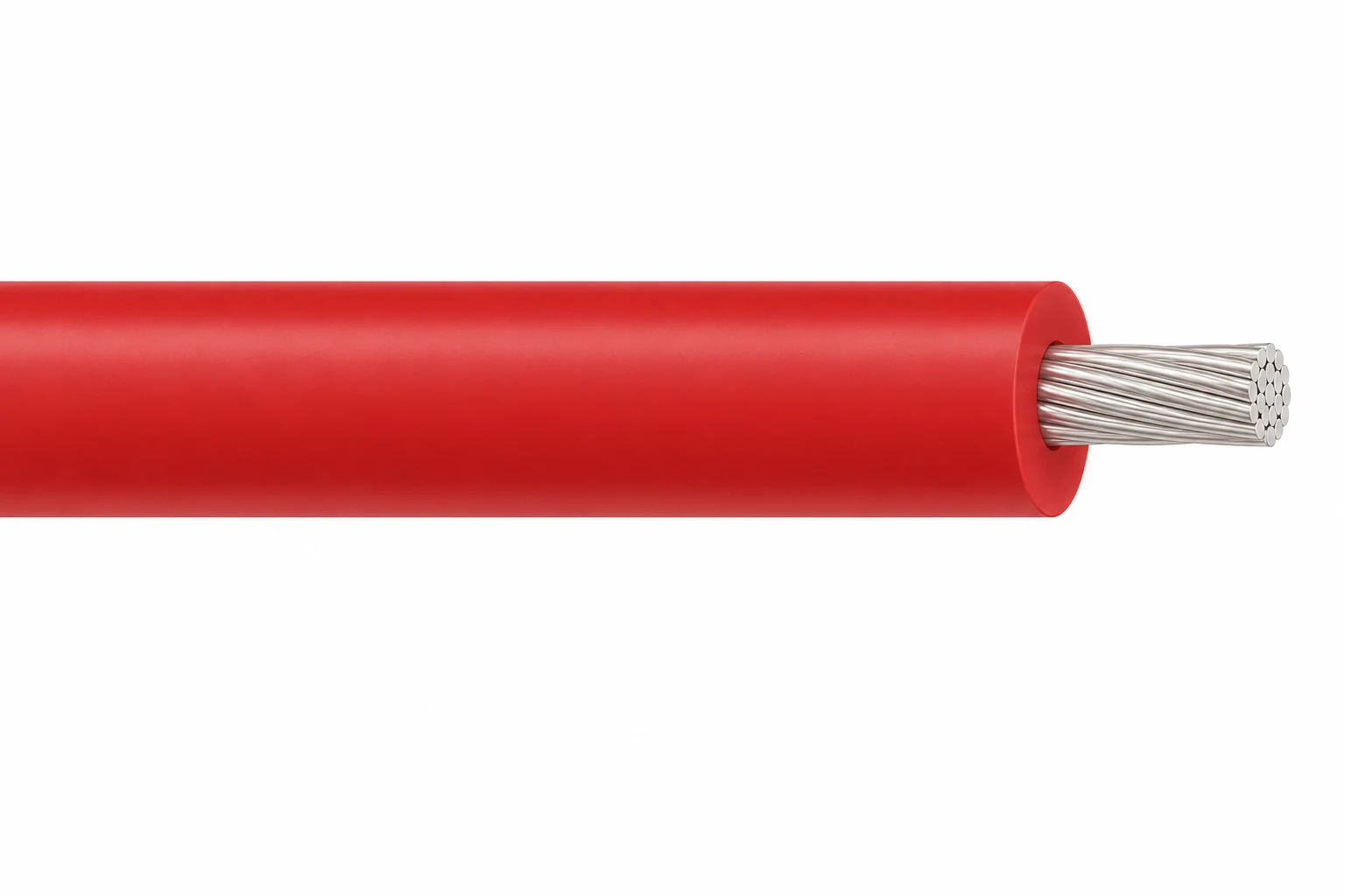
High Voltage Silicone Wire, 3–60 kV DC
A related cable option for a different application or duty profile.
View productRequest a cable recommendation and quotation
Send the required services, cable length, mechanical duty, environment, termination and quantity. Our team will review the application before quoting.
- Include the product name or SKU plus the required cable length and quantity.
- Attach a specification, drawing or data sheet when available.