





Drilling Mast Cable 600–2000 V — Blast-Hole Drill Power and Control Cable
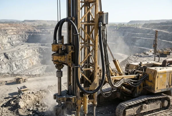
Heavy-duty 600–2000 V round two-conductor drilling mast cable for surface rotary blast-hole drill rigs, drill masts, festoons, suspended loops and power tracks. Built with extra-flexible ASTM B-33 tinned copper power conductors, 90 °C EPR insulation, an interstitial tinned-copper ground wire, a user-specified control group and a polypropylene-braid-reinforced thermosetting rubber jacket.
Drilling mast cable 600–2000 V is a combined power and control cable engineered for rotary blast-hole drill masts, DC drive systems, festoons, suspended loops and moving power tracks on surface mining equipment. In a single round assembly, it integrates two extra-flexible power conductors, an uninsulated equipment grounding conductor and a jacketed multi-conductor control group so mast travel loops do not require separate bundled power and control leads.
Each power core uses rope-lay stranded ASTM B-33 tinned soft or annealed copper insulated with 90 °C ethylene-propylene rubber (EPR). From 1/0 AWG through 500 kcmil, high strand counts—ranging from 266 wires in 1/0 AWG to 1,221 wires in 500 kcmil—preserve flexing endurance across repeated vertical carriage travel along the drill mast.
Over the cabled core assembly, a non-conducting separator tape and an integral polypropylene reinforcing braid inside the mold-cured thermosetting rubber jacket resist mechanical elongation, abrasion, impact, oil, flame, ozone, acids and alkalis. When the cable is installed on a multi-layer drum reel rather than an open mast loop, apply the wound-layer ampacity correction factors from one to four layers.
Specify the required power conductor size (1/0 AWG to 500 kcmil), control-group core count and gauge, mast travel stroke or reel layer count, and termination glands with your enquiry. TEBAOFLEX manufactures custom lengths from a 50 m minimum order quantity with a standard lead time of 7–45 working days.
Explore the mining and tunneling cable range for related configurations.
For 2000 V NEMA WC 58 portable mining power and trailing cables on drill rigs, compare these constructions: Type G-GC Cable 2000V Portable Mining Power Cable (for 3-conductor power with symmetrical grounds and a ground-check pilot conductor); Type W Cable 2000V – Round 4/C, 3/C and Flat Options (for heavy-duty 2000 V round and flat power drops without an internal ground-check core). Verify mast loop radius, low-temperature cold-bend rating, and conductor count before ordering.
Construction
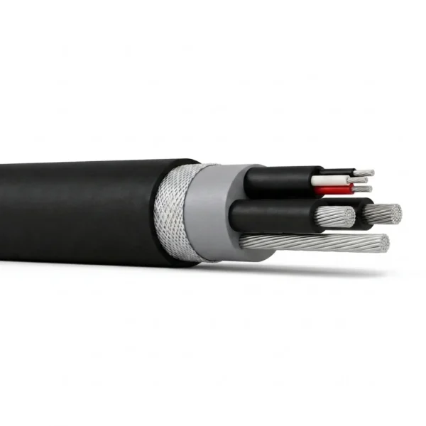
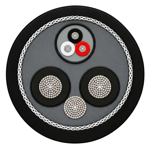
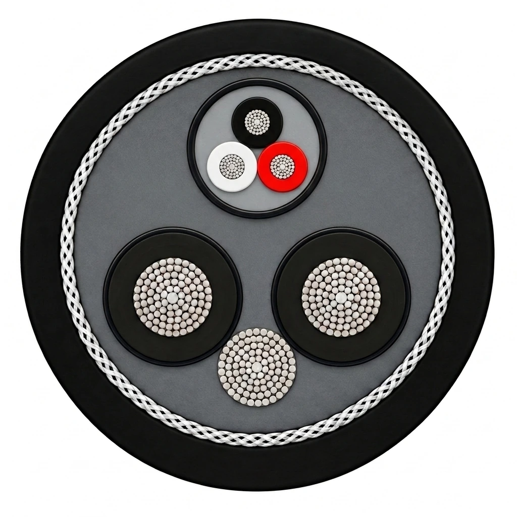
The representative construction illustrates 600–2000 V Drilling Mast Cable 2 × 4/0 AWG + Ground + 3-Core Control Group: two equal black EPR-insulated tinned-copper power cores at the lower left and right, one jacketed three-core control sub-assembly (black, white and red control cores) at the top, and one uninsulated flexible tinned-copper ground wire in the bottom interstitial valley, wrapped with non-conducting tape and enclosed in a polypropylene-braid-reinforced black thermosetting rubber jacket.
| Component | Material and construction |
|---|---|
| Power conductors | Two extra-flexible rope-lay stranded tinned soft or annealed copper conductors complying with ASTM B-33 (266 minimum wires in 1/0 AWG up to 1,221 minimum wires in 500 kcmil). |
| Power core insulation | Ethylene-propylene rubber (EPR) rated for +90 °C continuous conductor operation; nominal wall thickness 0.080 in (2.03 mm) for 1/0–4/0 AWG and 0.095 in (2.41 mm) for 250–500 kcmil. |
| Control group | Round jacketed control sub-assembly cabled in the upper interstice; representative configuration contains three insulated flexible tinned-copper control conductors (black, white, red). Exact control core count and size are specified by the user. |
| Grounding conductor | One uninsulated flexible stranded tinned-copper ground wire positioned in the lower interstitial valley between the two power conductors. |
| Separator tape | Non-conducting binder tape helically applied over the complete cabled core assembly to maintain round geometry during flexing. |
| Reinforcing braid | Open-weave polypropylene reinforcing braid embedded within the jacket wall to control axial stretch and extend vertical flex life. |
| Outer jacket | Heavy-duty reinforced mold-cured thermosetting rubber in black, resistant to abrasion, impact, heat, oil, flame, ozone, alkalis and acids, with permanent surface identification. |
Applications
Select the power conductor gauge and control-group configuration to match the drill mast drive current, auxiliary control circuits and suspension or reeling hardware.
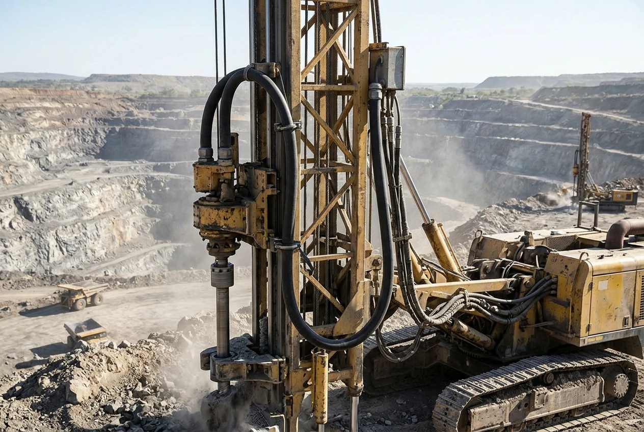
- Surface mining rotary blast-hole drill rigs: vertical mast loop feeding DC or AC rotary head drives and mast control circuits.
- Drill mast power tracks and guided carrier chains requiring high strand counts and controlled outside diameter tolerance (±5%).
- Heavy-duty suspended loops and festoon systems on mining, quarrying and bulk material-handling machinery.
- Multi-layer cable reels on mobile drilling and excavation equipment, sized using the 1-to-4 layer ampacity derating factors.
- Route the round cable through smooth saddle clamps or roller guides with generous bend radius, and anchor strain-relief grips at both the fixed mast structure and moving carriage so the electrical conductors never support mechanical hoist loads.
When specifying power feeds for underground drill jumbos and rotary blast-hole drills, consult these resources: Type G-GC Cable Solution for Underground Drill Jumbos (for 2 kV trailing reel cables feeding electro-hydraulic underground face drills); SHD-GC Cable 2kV-25kV Mining Power Cable (for 2 kV to 25 kV shielded trailing cables supplying high-voltage pit drills and shovels). Confirm vertical mast travel, jacket oil/mud resistance, and strain relief hardware.
Specifications
| Parameter | Value |
|---|---|
| Rated voltage range | 600–2,000 V |
| Maximum continuous conductor temperature | +90 °C |
| Ampacity reference ambient temperature | +40 °C ambient air, continuous duty |
| Power conductor material and stranding | ASTM B-33 flexible tinned soft or annealed copper; 266 to 1,221 minimum wires per conductor |
| Insulation compound | 90 °C Ethylene-Propylene Rubber (EPR) |
| Control group arrangement | Included; multi-conductor control sub-assembly configured to user specification |
| Equipment grounding conductor | Included; flexible stranded tinned copper ground wire |
| Reinforcement and outer jacket | Non-conducting separator tape, polypropylene reinforcing braid and mold-cured thermosetting rubber jacket |
| Dimensional and weight tolerance | ±5% manufacturing tolerance on nominal outside diameter and approximate cable weight |
| Commercial supply terms | Minimum order quantity 50 m; manufacturing lead time 7–45 working days depending on size and custom control-group specification |
| Power conductor size (AWG / kcmil) | Minimum wires per power conductor | Nominal insulation thickness (in / mm) | Nominal outside diameter (in / mm) | Approx. weight (lb/1,000 ft / kg/km) | Continuous ampacity at 90 °C / 40 °C (A) | Control group | Ground wire |
|---|---|---|---|---|---|---|---|
| 1/0 AWG | 266 | 0.080 / 2.03 | 1.52 / 38.6 | 1,780 / 2,649 | 217 | User specified | Included |
| 2/0 AWG | 323 | 0.080 / 2.03 | 1.65 / 41.9 | 2,425 / 3,609 | 250 | User specified | Included |
| 3/0 AWG | 418 | 0.080 / 2.03 | 1.77 / 45.0 | 2,872 / 4,274 | 286 | User specified | Included |
| 4/0 AWG | 532 | 0.080 / 2.03 | 1.92 / 48.8 | 3,478 / 5,176 | 328 | User specified | Included |
| 250 kcmil | 627 | 0.095 / 2.41 | 2.10 / 53.3 | 4,155 / 6,183 | 363 | User specified | Included |
| 350 kcmil | 888 | 0.095 / 2.41 | 2.36 / 59.9 | 5,483 / 8,160 | 436 | User specified | Included |
| 500 kcmil | 1,221 | 0.095 / 2.41 | 2.70 / 68.6 | 7,249 / 10,788 | 524 | User specified | Included |
| Number of wound layers on reel | Ampacity multiplying factor |
|---|---|
| 1 layer | 0.85 |
| 2 layers | 0.65 |
| 3 layers | 0.45 |
| 4 layers | 0.35 |
Metric insulation thicknesses, nominal outside diameters and approximate cable masses in kg/km are rounded engineering conversions of the primary imperial specification values.
Listed continuous-duty ampacities are calculated for a +90 °C conductor temperature in +40 °C ambient air with the cable in free air (such as a suspended mast loop or festoon).
When the cable is wound on a drum reel, multiply the single-cable free-air ampacity by the applicable reel correction factor for 1, 2, 3 or 4 wound layers.
Nominal cable outside diameters and weights are subject to a ±5% manufacturing tolerance. Confirm gland entry range and clamp saddle bore against the tolerance band before installation.
Every size includes the interstitial tinned-copper ground wire and space for the user-specified control group; state the required number and gauge of control cores when requesting a quotation.
Standards
| Standard or specification | Application |
|---|---|
| ICEA S-75-381 / NEMA WC-58 | Material and construction requirements for portable and power feeder cables used in mines and similar applications. |
| CSA C22.2 No. 96 | Canadian electrical safety and material performance requirements for portable power cables. |
| ASTM B-33 | Standard specification for tin-coated soft or annealed copper wire used in the flexible power, ground and control conductors. |
Related cable options
Compare these cable options by service combination, movement, load, voltage and transmission requirement.
SHD-GC Cable 2kV-25kV Mining Power Cable
A related cable option for a different application or duty profile.
View product
Type G-GC Cable 2000V Portable Mining Power Cable
A related cable option for a different application or duty profile.
View product
Type W Cable 2000V – Round 4/C, 3/C and Flat Options
A related cable option for a different application or duty profile.
View productRequest a cable recommendation and quotation
Send the required services, cable length, mechanical duty, environment, termination and quantity. Our team will review the application before quoting.
- Include the product name or SKU plus the required cable length and quantity.
- Attach a specification, drawing or data sheet when available.