








O2nGcekż/w-G(W) 3.6/6 kV Double-Screened Mining Cable
O2nGcekż/w-G(W) 3.6/6 kV cable combines EPR-insulated screened power cores, an overall copper screen and two polychloroprene sheaths. Choose a pilot-free, three-pilot or three-pair configuration; the -GW option adds longitudinal water-swelling tapes.
O2nGcekż/w-G(W) is a 3.6/6 kV flexible mining cable for trailing supplies to mobile mining and industrial machinery. Individual copper composite screens surround the EPR-insulated power cores, while a second, concentric copper screen surrounds the inner sheath. An ON5 inner sheath and ON4 outer sheath form the double polychloroprene construction. This arrangement must be specified as a complete cable system when replacing a screened trailing lead.
The family offers three distinct auxiliary arrangements. The pilot-free version has three screened power cores and distributed bare protective conductors. The three-pilot version places a pilot/earth unit in each outer interstice. The six-pilot version uses three screened pairs. The designations 4, 7 and 10 count the protective function as one; they are not a literal count of separate insulated cores. The final number in each configuration gives the nominal protective area, rather than the area of every individual earth element.
Select the full -G or -GW designation in the enquiry. The -GW construction adds tapes that swell in contact with moisture to restrict longitudinal water movement. This feature does not define an unlimited immersion rating. The tables separate the available core arrangements from configurations with stated cable diameters, helping match the cable to glands, connectors and handling equipment. TEBAOFLEX supplies this family from a 50 m minimum order, with a lead time of 7–45 working days. Include the voltage, power size, pilot arrangement, protective circuit, sealing option and actual trailing conditions for a matched quotation.
Where 3.6/6 kV underground mine distribution shifts from flexible trailing duty to fixed roadway, incline or shaft-zone installation requiring copper-tape core screens and galvanized round steel wire armour, see: YHKGYFoyn 3.6/6 kV Individually Screened Steel-Wire-Armoured Underground Mine Power Cable.
Explore the mining and tunneling cable range for related configurations.
Construction
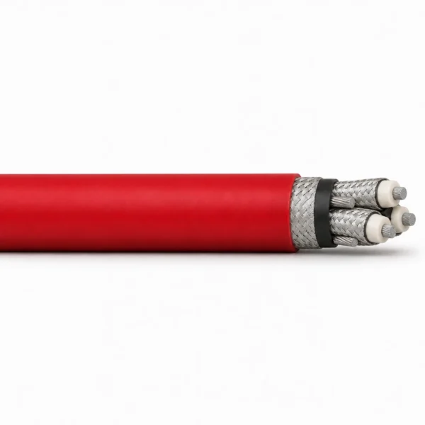
The double-screen system consists of individual power-core screens and a separate concentric screen over the inner sheath. Protective-conductor and pilot layouts change with the 4-, 7- or 10-functional-conductor construction; the main image shows the pilot-free 3 × 95 + 35 mm² base -G build.
| Component | Material and construction |
|---|---|
| Power conductors | Class 5 flexible tinned copper to the PN EN 60228 conductor reference. |
| Separator | Polyester foil or another non-hygroscopic separator over each power conductor. |
| Insulation | EPR type IEP insulation on power and pilot conductors; EPR also forms the auxiliary-unit sheath where applicable. |
| Individual screens | Non-hygroscopic semiconductive tape beneath a composite tinned-copper/plastic-yarn braid; minimum braid coverage 65%. |
| Pilot-free construction | Three screened power cores with three bare protective conductors distributed in the outer interstices, laid around a filler. |
| Three-pilot construction | Three pilot/earth units between the power cores. Each pilot conductor is wrapped around a rubber filler, insulated with EPR and surrounded by a tinned-copper protective-conductor wrap. |
| Six-pilot construction | Three pairs of insulated pilots, each pair jacketed and screened with tinned-copper wires, located between the screened power cores. |
| Cradle and fillers | Semiconductive type P rubber components where required by the selected layout. |
| Inner sheath | Polychloroprene thermosetting compound, type ON5. |
| Concentric screen | Overall tinned-copper/polyamide-yarn braid over a nonmetallic screen outside the inner sheath. |
| Longitudinal sealing option | Water-swelling tapes for the -GW construction. |
| Outer sheath | Polychloroprene thermosetting compound, type ON4; red or black. |
Applications
Use the complete power, pilot, protective-conductor and screen arrangement to match the machine circuit and cable-handling conditions.
- Trailing power supply to mobile mining and industrial machines operating within the 3.6/6 kV rating.
- Heavy-duty routes where abrasion, tearing and oil exposure influence the choice of outer sheath.
- Machine connections requiring both individual power-core screens and a separate overall copper screen.
- Circuits needing no pilots, three pilots or three screened pilot pairs, using the corresponding protective-conductor layout.
- Routes requiring longitudinal water-blocking tapes, when the -GW option and termination sealing are explicitly specified.
- Replacement projects where cable diameter, protective-circuit continuity and screen terminations must match the machine and connectors.
For route and construction selection, see our mining and tunnelling cable solutions.
For a chain-handled coal-cutter connection, compare NTSKCGEcWÖU coal-cutter chain cable. Check its concentric control/protective-conductor arrangement and mechanical protection against the double-screen construction required here.
For a different three-power, earth-and-pilot trailing arrangement, review NTSKCGEWÖU 3.6/6 kV trailing cable. Match the protective circuits, pilot function and sheath system before selecting a replacement.
For fixed armoured feeder or control routes, see TECK90 600 V / 1 kV armoured control and power cable. This is a different installation duty; it is not a replacement for a moving trailing cable.
Specifications
| Parameter | Value |
|---|---|
| Rated voltage U₀/U | 3.6/6 kV |
| Power-conductor range | 25, 35, 50, 70, 95 and 120 mm² in the listed discrete configurations |
| Auxiliary arrangements | No pilots; three pilots; or three pairs of pilots |
| Nominal protective areas | 16, 25 or 35 mm², allocated by the selected configuration |
| Screen system | Individual power-core screens plus a concentric overall screen |
| Individual braid coverage | Minimum 65% |
| Sheath system | ON5 inner and ON4 outer polychloroprene sheaths |
| Longitudinal sealing | Water-swelling tapes in -GW builds |
| Maximum conductor temperature | 90°C |
| Ambient and handling limits | Specify the operating temperature, bend radius and pulling conditions for the order |
| Sheath characteristics | Oil resistance and flame-retardant behaviour; abrasion and tear resistance |
| Minimum order | 50 m |
| Lead time | 7–45 working days |
| Model and configuration | Functional conductor class | Auxiliary arrangement | Total nominal protective area (mm²) |
|---|---|---|---|
| O2nGcekż/w-G(W) 3.6/6 kV — 3 × 25 + 16 mm² | 4 | None | 16 |
| O2nGcekż/w-G(W) 3.6/6 kV — 3 × 35 + 16 mm² | 4 | None | 16 |
| O2nGcekż/w-G(W) 3.6/6 kV — 3 × 50 + 25 mm² | 4 | None | 25 |
| O2nGcekż/w-G(W) 3.6/6 kV — 3 × 70 + 25 mm² | 4 | None | 25 |
| O2nGcekż/w-G(W) 3.6/6 kV — 3 × 95 + 35 mm² | 4 | None | 35 |
| O2nGcekż/w-G(W) 3.6/6 kV — 3 × 120 + 35 mm² | 4 | None | 35 |
| O2nGcekż/w-G(W) 3.6/6 kV — 3 × 25 + 3 × 2.5 + 16 mm² | 7 | Three 2.5 mm² pilots in three pilot/earth units | 16 |
| O2nGcekż/w-G(W) 3.6/6 kV — 3 × 35 + 3 × 2.5 + 16 mm² | 7 | Three 2.5 mm² pilots in three pilot/earth units | 16 |
| O2nGcekż/w-G(W) 3.6/6 kV — 3 × 50 + 3 × 2.5 + 25 mm² | 7 | Three 2.5 mm² pilots in three pilot/earth units | 25 |
| O2nGcekż/w-G(W) 3.6/6 kV — 3 × 70 + 3 × 4 + 25 mm² | 7 | Three 4 mm² pilots in three pilot/earth units | 25 |
| O2nGcekż/w-G(W) 3.6/6 kV — 3 × 95 + 3 × 4 + 35 mm² | 7 | Three 4 mm² pilots in three pilot/earth units | 35 |
| O2nGcekż/w-G(W) 3.6/6 kV — 3 × 120 + 3 × 4 + 35 mm² | 7 | Three 4 mm² pilots in three pilot/earth units | 35 |
| O2nGcekż/w-G(W) 3.6/6 kV — 3 × 25 + 3 × 2 × 2.5 + 16 mm² | 10 | Three pairs of 2.5 mm² pilots | 16 |
| O2nGcekż/w-G(W) 3.6/6 kV — 3 × 35 + 3 × 2 × 2.5 + 16 mm² | 10 | Three pairs of 2.5 mm² pilots | 16 |
| O2nGcekż/w-G(W) 3.6/6 kV — 3 × 50 + 3 × 2 × 2.5 + 25 mm² | 10 | Three pairs of 2.5 mm² pilots | 25 |
| O2nGcekż/w-G(W) 3.6/6 kV — 3 × 50 + 3 × 2 × 4 + 25 mm² | 10 | Three pairs of 4 mm² pilots | 25 |
| O2nGcekż/w-G(W) 3.6/6 kV — 3 × 70 + 3 × 2 × 4 + 25 mm² | 10 | Three pairs of 4 mm² pilots | 25 |
| O2nGcekż/w-G(W) 3.6/6 kV — 3 × 70 + 3 × 2 × 6 + 25 mm² | 10 | Three pairs of 6 mm² pilots | 25 |
| O2nGcekż/w-G(W) 3.6/6 kV — 3 × 95 + 3 × 2 × 4 + 35 mm² | 10 | Three pairs of 4 mm² pilots | 35 |
| O2nGcekż/w-G(W) 3.6/6 kV — 3 × 95 + 3 × 2 × 6 + 35 mm² | 10 | Three pairs of 6 mm² pilots | 35 |
| O2nGcekż/w-G(W) 3.6/6 kV — 3 × 120 + 3 × 2 × 4 + 35 mm² | 10 | Three pairs of 4 mm² pilots | 35 |
| O2nGcekż/w-G(W) 3.6/6 kV — 3 × 120 + 3 × 2 × 6 + 35 mm² | 10 | Three pairs of 6 mm² pilots | 35 |
| Model and configuration | Minimum OD (mm) | Approx. OD (mm) | Maximum OD (mm) |
|---|---|---|---|
| O2nGcekż/w-G(W) 3.6/6 kV — 3 × 95 + 35 mm² | 60.0 | 61.3 | 66.0 |
| O2nGcekż/w-G(W) 3.6/6 kV — 3 × 120 + 35 mm² | 60.1 | 65.3 | 69.0 |
| O2nGcekż/w-G(W) 3.6/6 kV — 3 × 25 + 3 × 2.5 + 16 mm² | 48.0 | 50.9 | 54.0 |
| O2nGcekż/w-G(W) 3.6/6 kV — 3 × 35 + 3 × 2.5 + 16 mm² | 60.0 | 63.2 | 66.5 |
| O2nGcekż/w-G(W) 3.6/6 kV — 3 × 50 + 3 × 2.5 + 25 mm² | 62.0 | 64.9 | 68.0 |
| O2nGcekż/w-G(W) 3.6/6 kV — 3 × 70 + 3 × 4 + 25 mm² | 63.0 | 67.0 | 70.3 |
| O2nGcekż/w-G(W) 3.6/6 kV — 3 × 95 + 3 × 4 + 35 mm² | 69.0 | 73.3 | 77.0 |
| O2nGcekż/w-G(W) 3.6/6 kV — 3 × 50 + 3 × 2 × 2.5 + 25 mm² | 62.0 | 64.9 | 68.0 |
| O2nGcekż/w-G(W) 3.6/6 kV — 3 × 50 + 3 × 2 × 4 + 25 mm² | 62.0 | 64.9 | 68.0 |
| O2nGcekż/w-G(W) 3.6/6 kV — 3 × 70 + 3 × 2 × 4 + 25 mm² | 64.0 | 67.0 | 70.0 |
| O2nGcekż/w-G(W) 3.6/6 kV — 3 × 70 + 3 × 2 × 6 + 25 mm² | 64.0 | 67.0 | 70.0 |
| O2nGcekż/w-G(W) 3.6/6 kV — 3 × 95 + 3 × 2 × 4 + 35 mm² | 70.0 | 73.5 | 77.0 |
| O2nGcekż/w-G(W) 3.6/6 kV — 3 × 95 + 3 × 2 × 6 + 35 mm² | 70.0 | 73.5 | 77.0 |
Configuration areas are in mm². In the configuration notation, the first term identifies three power cores, any middle term identifies pilots, and the final term is the nominal protective area.
Functional conductor classes 4, 7 and 10 count the protective function once. They do not mean four, seven or ten individually insulated cores. In the pilot-free build, the earth conductors are distributed in three outer interstices.
The notation 3 × 2 × 4 means three pairs of 4 mm² pilots. It does not mean three 8 mm² pilot conductors.
Use only the listed discrete combinations. A power-size range does not make every pilot size and protective area interchangeable.
Overall dimensions are provided only for the listed rows. Confirm the finished diameter and tolerance for the selected -G or -GW construction before choosing glands, connectors and cable-handling hardware.
Specify the required current, duty cycle, ambient conditions and handling arrangement for rating selection. No universal current, reel speed, bend radius or pulling-tension value is assigned to all configurations on this page.
The 90°C limit refers to the conductor. Agree ambient and handling temperatures separately for the intended installation.
Water-swelling tapes in -GW limit longitudinal water movement. Fluid compatibility, immersion depth and duration, end sealing and entry protection require separate specification.
Coordinate the protective conductor, individual screens and overall-screen terminations with the machine protection and earthing system. Pilot cores do not replace the protective circuit.
Standards
| Standard or specification | Application |
|---|---|
| ZN-KFK-011:1999 | Construction specification reference for the double-screen 3.6/6 kV family; agree the detailed build and required edition in the purchase specification. |
| PN EN 60228 | Flexible tinned-copper power-conductor reference; the selected construction uses Class 5 conductors. |
| PN-89/E-29100 | Legacy compound references: EPR IEP insulation, semiconductive P components, ON5 inner sheath and ON4 outer sheath. |
Official standards and approval references
Conductor and compound references describe parts of the construction. They do not by themselves establish product approval for a particular mine or hazardous location.
Specify the required flame-test method, acceptance documents and standard editions with the enquiry. General flame-retardant characteristics do not establish circuit integrity in a fire.
- IEC 60228:2023 — Conductors of insulated cables — Official scope covering conductor cross-sectional areas, wire construction and resistance, including flexible copper conductors. The required conductor-standard edition must be agreed for the selected cable.
Certifications and document support
Review our company certificates and document scopes when identifying the documentation required for the quoted construction.
Provide the destination mine, full -G or -GW designation, voltage, power/pilot/protective arrangement and required approval or test documents. Identify the individual and overall-screen termination method, operating temperatures and handling duty so the quotation and supporting documents refer to the same construction.
Related cable options
Compare these cable options by service combination, movement, load, voltage and transmission requirement.
NTSKCGECWOEU 1.8/3–3.6/6 kV Coal Cutter Chain Cable
A related cable option for a different application or duty profile.
View product
(N)TSKCGEWÖU 3.6/6kV Medium Voltage Mining Trailing Cable
For 3.6/6 kV trailing duty behind mobile mining equipment.
View product
TECK90 600 V / 1 kV Armoured Control and Power Cable
A related cable option for a different application or duty profile.
View productRequest a cable recommendation and quotation
Send the required services, cable length, mechanical duty, environment, termination and quantity. Our team will review the application before quoting.
- Include the product name or SKU plus the required cable length and quantity.
- Attach a specification, drawing or data sheet when available.