








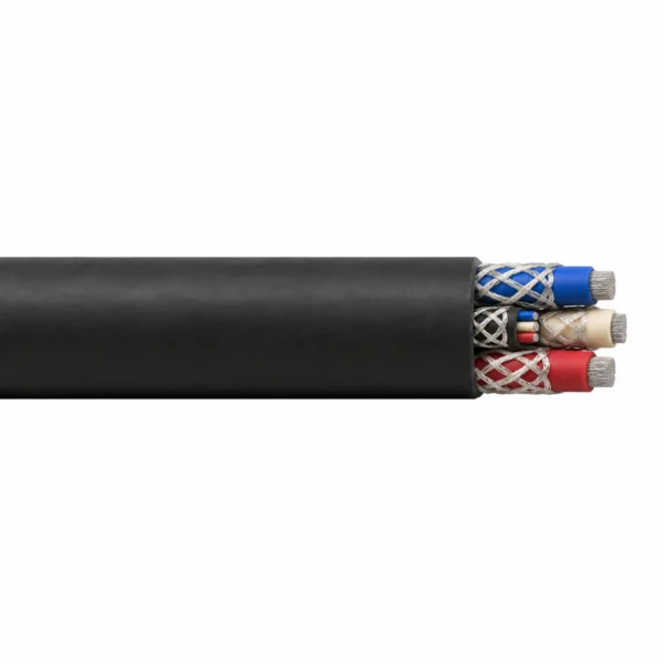
OnGcekż-G 0.6/1 & 3.6/6 kV Screened Mining Cable
OnGcekż-G combines three individually screened EPR power cores, a screened group of three or six pilots and a bare earth conductor beneath one polychloroprene sheath. The 0.6/1 kV and 3.6/6 kV constructions have separate screen coverage and sizing data.
OnGcekż-G is a flexible screened trailing cable for mobile mining and industrial equipment. Three EPR-insulated power cores and a screened pilot group are laid around a bare tinned-copper earth conductor. A single polychloroprene sheath protects the assembly. The grouped pilots provide separate auxiliary connections while the central earth remains a distinct protective circuit; the pilot group is not a substitute for the earth conductor.
Choose the voltage construction before selecting the conductor sizes. The 0.6/1 kV version has individual power screens with 30% composite-braid coverage and a black outer sheath. The 3.6/6 kV version uses a minimum 65% coverage and is listed with red or black sheathing. Both versions offer discrete configurations with three or six pilots, but their wall thicknesses, diameters and electrical data differ. The tables keep the two voltage families separate so the same power area is not mistaken for an interchangeable finished cable.
This design suits trailing connections exposed to mechanical wear, with cable selection tied to the machine circuit and actual handling route. Confirm the full power/earth/pilot arrangement, screen connections, operating current and available cable-entry space together. The medium-voltage table includes configuration-specific tension values; the low-voltage construction has an 8 × diameter minimum bend-radius reference. TEBAOFLEX supplies this family from a 50 m minimum order, with a lead time of 7–45 working days. Include voltage, complete core sizes, ambient conditions and connector or reel details to obtain the appropriate construction and supporting documents.
For smaller 0.6/1 kV auxiliary power and control circuits (1.5 to 25 mm²) requiring an individual tinned-copper braid screen on every power and pilot core around a central bare earth conductor under ZN-96/MP-13-K1176, see: OnGcekżi-G 0.6/1 kV Individually Screened Intrinsically Safe & Control Mining Cable.
Explore the mining and tunneling cable range for related configurations.
Construction
This family has one overall polychloroprene sheath. Each power core is screened individually, while the pilots form a separately screened group. The main illustration represents the 0.6/1 kV 3 × 35 + 16 + 3 × 2.5 mm² construction; medium-voltage layers and dimensions are specified separately.
| Component | Material and construction |
|---|---|
| Power conductors | Flexible stranded tinned copper to the PN EN 60228 conductor reference. |
| Separator | Polyester tape over the power conductors. |
| Insulation | EPR type IEP to the PN-89/E-29100 compound reference. |
| 0.6/1 kV power screens | Semiconducting tape and a composite tinned-copper/fibre braid with 30% coverage. |
| 3.6/6 kV power screens | Semiconducting tape and a composite tinned-copper/fibre braid with minimum 65% coverage. |
| Pilot group | Three or six insulated tinned-copper pilots grouped and screened. The 3.6/6 kV construction specifies a stranded, jacketed group with a copper/fibre braid screen. |
| Earth conductor | One bare flexible tinned-copper earth at the centre of the laid-up assembly. The medium-voltage construction specifies Class 5 annealed tinned copper. |
| Assembly | Three screened power cores and the screened pilot group laid around the earth conductor. The low-voltage construction includes rubber interstitial fillers and a polyester binder. |
| Outer sheath | One polychloroprene thermosetting sheath using the ON4 compound reference. Black for 0.6/1 kV; red or black for 3.6/6 kV. |
| Core identification | 0.6/1 kV: blue, natural and red, with black/grey/brown as the Czech-market alternative. 3.6/6 kV: black, brown and grey power cores; brown, black and grey pilots. Confirm the identification schedule for six-pilot builds. |
Applications
Select the voltage, pilot group and central-earth size for the connected machine, then verify the cable route and terminations against that complete configuration.
- Flexible trailing supply to mobile mining and industrial machines within the selected 0.6/1 kV or 3.6/6 kV rating.
- Connections needing three power cores, three or six auxiliary pilot cores and a separate protective-earth conductor.
- Heavy-duty service exposed to abrasion, tearing and oil, using the specified polychloroprene sheath.
- Medium-voltage mobile-equipment connections where configuration-specific cable diameter and maximum recommended tension govern handling.
- Replacement leads requiring coordinated power-screen, pilot-group screen and protective-earth terminations.
- Machine routes where bending, cable support and any reel duty are reviewed for the installation rather than inferred from voltage alone.
For route and construction selection, see our mining and tunnelling cable solutions.
For a different low-voltage coal-cutter control/protective-conductor arrangement, compare NSSHkCGEÖU 0.6/1 kV coal-cutter cable. Match its conductor layout and sheath system to the machine; a shared voltage rating does not establish interchangeability.
For a 3.6/6 kV trailing design with a different earth-and-pilot allocation, review NTSKCGEWÖU 3.6/6 kV trailing cable. Compare the individual protective circuits and pilot arrangement with this central-earth, grouped-pilot construction.
For fixed armoured feeder or control routes, see TECK90 600 V / 1 kV armoured control and power cable. This is a different installation duty; it is not a replacement for a moving trailing cable.
Specifications
| Parameter | Value |
|---|---|
| Rated voltages U₀/U | 0.6/1 kV and 3.6/6 kV as separate constructions |
| Low-voltage power sizes | 25, 35, 50, 70, 95 and 120 mm² in the listed configurations |
| Medium-voltage power sizes | 35, 50, 70, 95 and 120 mm² in the listed configurations |
| Pilot count | Three or six, as stated in each row |
| Earth arrangement | Separate bare central tinned-copper conductor |
| Power-screen coverage | 30% for 0.6/1 kV; minimum 65% for 3.6/6 kV |
| Overall sheath | Single polychloroprene sheath |
| Ambient temperature | −35°C to +55°C |
| Maximum conductor temperature | 90°C |
| 0.6/1 kV minimum bend radius | 8 × cable diameter; confirm suitability for the actual handling duty |
| 3.6/6 kV AC voltage-test references | 11 kV on power cores; 2 kV on pilot cores |
| Sheath characteristics | Oil resistance and flame-retardant behaviour; resistance to abrasion and tearing |
| Minimum order | 50 m |
| Lead time | 7–45 working days |
| Model and configuration | Listed insulation thickness (mm) | Outer sheath thickness (mm) | Listed OD (mm) | Approx. mass (kg/km) | Reference current (A) |
|---|---|---|---|---|---|
| OnGcekż-G 0.6/1 kV — 3 × 25 + 16 + 3 × 2.5 mm² | 1.5 | 5.0 | 37.0 | 2164 | 152 |
| OnGcekż-G 0.6/1 kV — 3 × 35 + 16 + 3 × 2.5 mm² | 1.6 | 5.0 | 38.8 | 2500 | 187 |
| OnGcekż-G 0.6/1 kV — 3 × 35 + 16 + 6 × 2.5 mm² | 1.6 | 5.0 | 40.3 | 2736 | 187 |
| OnGcekż-G 0.6/1 kV — 3 × 50 + 25 + 3 × 4 mm² | 1.7 | 5.5 | 45.2 | 3503 | 233 |
| OnGcekż-G 0.6/1 kV — 3 × 50 + 25 + 6 × 2.5 mm² | 1.7 | 5.5 | 45.2 | 3528 | 233 |
| OnGcekż-G 0.6/1 kV — 3 × 70 + 35 + 3 × 4 mm² | 1.8 | 5.5 | 50.0 | 4580 | 288 |
| OnGcekż-G 0.6/1 kV — 3 × 70 + 35 + 6 × 2.5 mm² | 1.8 | 5.5 | 50.0 | 4600 | 288 |
| OnGcekż-G 0.6/1 kV — 3 × 70 + 35 + 6 × 4 mm² | 1.8 | 5.5 | 50.7 | 4655 | 288 |
| OnGcekż-G 0.6/1 kV — 3 × 95 + 35 + 6 × 4 mm² | 2.0 | 6.4 | 58.0 | 5917 | 345 |
| OnGcekż-G 0.6/1 kV — 3 × 120 + 50 + 6 × 4 mm² | 2.2 | 6.4 | 60.6 | 6947 | 400 |
| Model and configuration | Nominal insulation thickness (mm) | Outer sheath thickness (mm) | Minimum OD (mm) | Approx. OD (mm) | Maximum OD (mm) | Approx. mass (kg/km) |
|---|---|---|---|---|---|---|
| OnGcekż-G 3.6/6 kV — 3 × 35 + 16 + 3 × 2.5 mm² | 3.4 | 5.5 | 47.0 | 50.1 | 53.0 | 3536 |
| OnGcekż-G 3.6/6 kV — 3 × 35 + 16 + 3 × 4 mm² | 3.4 | 5.5 | 47.0 | 50.1 | 53.0 | 3575 |
| OnGcekż-G 3.6/6 kV — 3 × 35 + 16 + 6 × 2.5 mm² | 3.4 | 5.5 | 47.0 | 50.1 | 53.0 | 3596 |
| OnGcekż-G 3.6/6 kV — 3 × 50 + 25 + 3 × 2.5 mm² | 3.4 | 5.5 | 52.5 | 54.9 | 58.0 | 4200 |
| OnGcekż-G 3.6/6 kV — 3 × 50 + 25 + 3 × 4 mm² | 3.4 | 5.5 | 52.5 | 54.9 | 58.0 | 4230 |
| OnGcekż-G 3.6/6 kV — 3 × 50 + 25 + 6 × 2.5 mm² | 3.4 | 5.5 | 52.5 | 54.1 | 58.0 | 4750 |
| OnGcekż-G 3.6/6 kV — 3 × 50 + 25 + 6 × 4 mm² | 3.4 | 5.5 | 52.5 | 54.9 | 58.0 | 4310 |
| OnGcekż-G 3.6/6 kV — 3 × 70 + 35 + 6 × 4 mm² | 3.4 | 5.5 | 55.6 | 58.6 | 62.0 | 5891 |
| OnGcekż-G 3.6/6 kV — 3 × 70 + 50 + 3 × 4 mm² | 3.4 | 5.5 | 58.0 | 63.0 | 68.0 | 4506 |
| OnGcekż-G 3.6/6 kV — 3 × 95 + 35 + 6 × 4 mm² | 3.4 | 6.4 | 62.0 | 65.4 | 69.0 | 7150 |
| OnGcekż-G 3.6/6 kV — 3 × 95 + 50 + 3 × 4 mm² | 3.4 | 6.4 | 62.5 | 65.7 | 69.5 | 7254 |
| OnGcekż-G 3.6/6 kV — 3 × 120 + 50 + 3 × 4 mm² | 3.4 | 6.4 | 65.0 | 68.3 | 73.0 | 8191 |
| Model and configuration | Reference current (A) | Maximum recommended tension (N) |
|---|---|---|
| OnGcekż-G 3.6/6 kV — 3 × 35 + 16 + 3 × 2.5 mm² | 180 | 1575 |
| OnGcekż-G 3.6/6 kV — 3 × 35 + 16 + 3 × 4 mm² | 180 | 1575 |
| OnGcekż-G 3.6/6 kV — 3 × 35 + 16 + 6 × 2.5 mm² | 180 | 1575 |
| OnGcekż-G 3.6/6 kV — 3 × 50 + 25 + 3 × 2.5 mm² | 222 | 2250 |
| OnGcekż-G 3.6/6 kV — 3 × 50 + 25 + 3 × 4 mm² | 222 | 2250 |
| OnGcekż-G 3.6/6 kV — 3 × 50 + 25 + 6 × 2.5 mm² | 222 | 2250 |
| OnGcekż-G 3.6/6 kV — 3 × 50 + 25 + 6 × 4 mm² | 222 | 2250 |
| OnGcekż-G 3.6/6 kV — 3 × 70 + 35 + 6 × 4 mm² | 275 | 3150 |
| OnGcekż-G 3.6/6 kV — 3 × 70 + 50 + 3 × 4 mm² | 275 | 3150 |
| OnGcekż-G 3.6/6 kV — 3 × 95 + 35 + 6 × 4 mm² | 328 | 4275 |
| OnGcekż-G 3.6/6 kV — 3 × 95 + 50 + 3 × 4 mm² | 328 | 4275 |
| OnGcekż-G 3.6/6 kV — 3 × 120 + 50 + 3 × 4 mm² | 379 | 5400 |
Configuration areas are in mm², in the order power + earth + pilots. For example, 3 × 35 + 16 + 3 × 2.5 means three 35 mm² power cores, one 16 mm² earth and three 2.5 mm² pilots.
Keep the 0.6/1 kV and 3.6/6 kV builds separate. Their individual power-screen coverages are 30% and minimum 65%, respectively; these figures do not specify the coverage of the pilot-group screen.
The low-voltage table gives a single listed outside diameter for each row. Obtain the agreed nominal diameter and manufacturing tolerance before selecting a gland or connector; do not treat that single figure as a guaranteed maximum.
The low-voltage insulation column is a listed construction reference. Confirm the power- and pilot-insulation wall requirements separately on the agreed drawing.
Reference currents must be checked against the installation thermal basis, ambient temperature, load cycle, grouping and any cable remaining on a drum. Do not assume a 25°C ambient basis or apply a laid-out rating unchanged to a wound cable.
The 8 × diameter bend-radius reference belongs to the low-voltage construction. Agree bending and handling limits for the selected medium-voltage build; no numeric speed or fatigue-cycle rating is assigned here.
Maximum recommended tension values are specific to the medium-voltage rows and are stated in newtons. Confirm the pulling attachment, route, support and dynamic loads before installation.
The 11 kV power and 2 kV pilot figures are AC test-voltage references for the 3.6/6 kV construction. They are not operating-voltage ratings; specify the required test duration and procedure with the order.
These tables describe the base -G construction. Water-blocked -GW and six-power-core -G2 designs require their own complete specification; do not add their suffixes to these rows without reviewing the resulting build.
Coordinate the power screens, pilot-group screen and bare earth with the protection and earthing scheme. Pilot cores do not replace the earth conductor.
Water exposure, immersion depth and duration, fluids and end sealing must be specified separately. A water-resistant sheath does not define an unlimited submersible-cable rating.
Use the complete listed configuration and confirm the final manufacturing drawing for ordering. Do not interpolate an unlisted pilot size, earth area, diameter or tension value.
Standards
| Standard or specification | Application |
|---|---|
| ZN-96/MP-13-K1172 | Construction specification reference for the low-voltage family; the medium-voltage construction is described in line with this reference. Agree the complete selected build in the purchase specification. |
| PN EN 60228 | Conductor construction reference for the flexible stranded tinned-copper power conductors. |
| PN-89/E-29100 | Legacy compound reference for IEP EPR insulation and ON4 polychloroprene sheathing. |
| 3.6/6 kV AC voltage tests | Power-core test reference 11 kV; pilot-core test reference 2 kV. Test duration and acceptance procedure are to be specified for the order. |
Official standards and approval references
Conductor, compound and construction references must be matched to the quoted voltage and core arrangement. A standards reference or test-voltage value does not establish approval for a particular mine or hazardous location.
Agree the required standard editions, flame-test method and acceptance documents before manufacture. Flame-retardant sheath behaviour does not establish fire circuit integrity.
- IEC 60228:2023 — Conductors of insulated cables — Official scope for conductor cross-sectional areas, wire construction and resistance, including flexible copper conductors. This conductor standard does not grant a mining-cable product approval.
Certifications and document support
Review our company certificates and document scopes when identifying the documentation required for the quoted construction.
Provide the destination mine, selected voltage, complete power/earth/pilot configuration and required test or product-acceptance documents. Include the operating current, thermal and handling conditions, screen termination method and any water exposure so the documentation can be matched to the quoted construction.
Related cable options
Compare these cable options by service combination, movement, load, voltage and transmission requirement.
NSSHKCGEOEU 0.6/1kV Coal Cutter Trailing Cable
A related cable option for a different application or duty profile.
View product
(N)TSKCGEWÖU 3.6/6kV Medium Voltage Mining Trailing Cable
For 3.6/6 kV trailing duty behind mobile mining equipment.
View product
TECK90 600 V / 1 kV Armoured Control and Power Cable
A related cable option for a different application or duty profile.
View productRequest a cable recommendation and quotation
Send the required services, cable length, mechanical duty, environment, termination and quantity. Our team will review the application before quoting.
- Include the product name or SKU plus the required cable length and quantity.
- Attach a specification, drawing or data sheet when available.