


(N)TMCGEH3S 6/10 kV Mining Trailing Cable
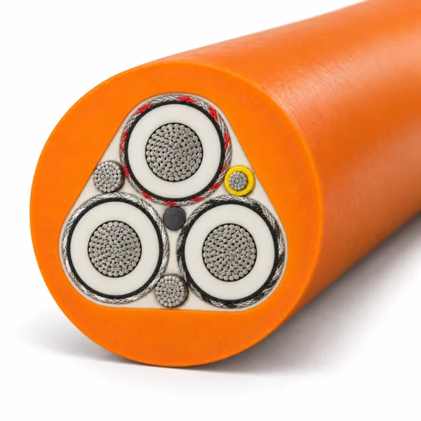
(N)TMCGEH3S 6/10 kV mining trailing cable supplies mobile mining equipment with three individually screened power cores, two earth conductors and a separate ground-check core. The featured configuration is 3 × 120 + 2 × 50 + 1 × 16 mm², with EPR insulation and an orange TPU outer sheath.
- Rated voltage: U₀/U 6/10 kV; Um 12 kV.
- Phase conductors: 3 × 120 mm², flexible class 5 tinned copper.
- Earth and pilot: 2 × 50 mm² earth + 1 × 16 mm² insulated ground-check conductor.
- Insulation: EPR type 3GI3; 90 °C conductor operating temperature.
- Screening: semiconductive layers and an individual mixed copper/textile braid over each phase.
- Outer sheath: orange extra-heavy-duty thermoplastic polyurethane.
- Construction reference: DIN VDE 0250-813.
For a technical quotation, send the cable length, equipment, movement pattern, site conditions and termination requirements.
(N)TMCGEH3S cable for mobile mining power
TEBAOFLEX (N)TMCGEH3S is a 6/10 kV mining trailing cable for electrical connections that move with the machine. The reference configuration is 3 × 120 + 2 × 50 + 1 × 16 mm²: three power conductors, two protective-earth conductors and one ground-check conductor in the same cable. It gives procurement and maintenance teams a clear starting point for matching the power circuit, grounding arrangement and monitoring circuit to an existing installation.
The separate pilot core matters when reviewing a replacement. A cable with a 10 mm² pilot, a different earth arrangement or an added optical unit has a different construction, even when the power-core size and voltage look similar. Match the complete designation and circuit allocation before comparing quotations. The reference data in Specifications support preliminary selection; the agreed cable drawing and project operating conditions govern the final order.
- Ordering focus: retain the full 3 × 120 + 2 × 50 + 1 × 16 mm² designation on the enquiry.
- Equipment interface: check the power termination, earth connections and ground-monitoring circuit together.
- Movement review: identify trailing duty and any drum or guide arrangement before selecting the cable.
- Installation fit: verify cable diameter, connector entry, route clearance and thermal conditions as one system.
Browse the mining and tunneling cable range or use the medium-voltage mining cable selection guide to prepare the installation information.
Construction
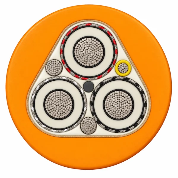
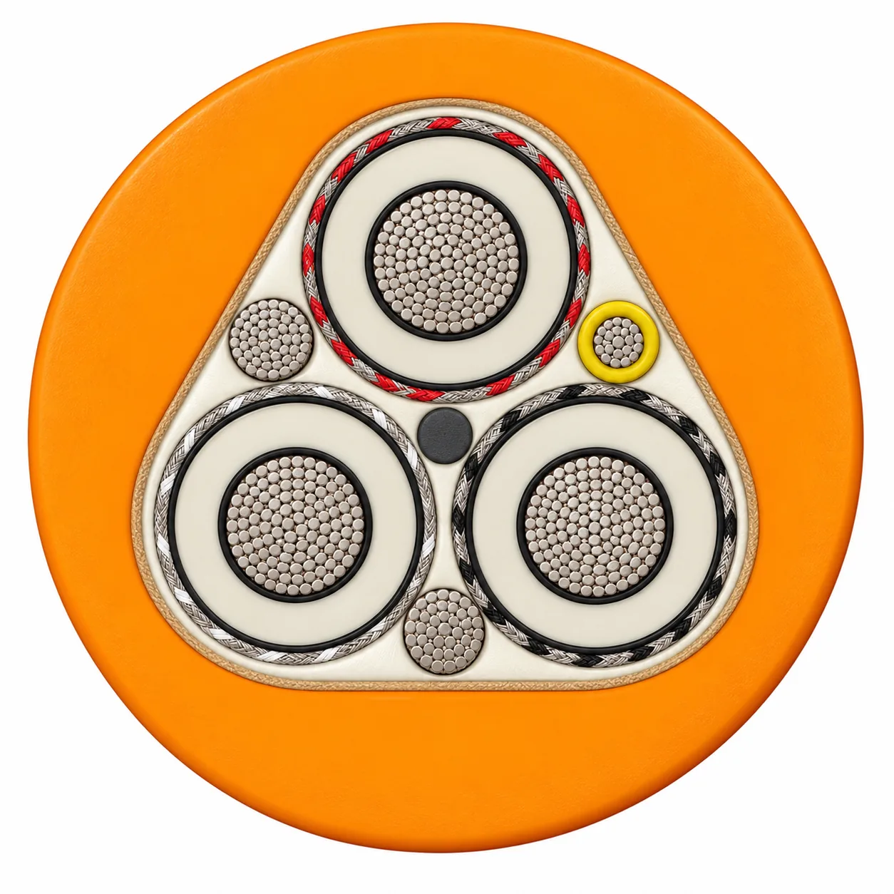
The (N)TMCGEH3S 3 × 120 + 2 × 50 + 1 × 16 mm² build uses three individually screened EPR power cores in a triangular lay-up. Two earth conductors and the insulated pilot occupy the spaces around the power cores, inside a reinforced assembly and orange TPU sheath.
| Layer / component | Construction specification |
|---|---|
| 1 — Phase conductors | 3 × 120 mm² finely stranded, flexible tinned copper; class 5 according to IEC 60228. |
| 2 — Conductor screen | Semiconductive rubber applied over each phase conductor for electrical field control. |
| 3 — EPR insulation | Thermosetting ethylene propylene rubber, type 3GI3 according to DIN VDE 0207 Part 20; 90 °C conductor operating temperature. |
| 4 — Insulation screen | Strippable semiconductive rubber over each phase insulation. |
| 5 — Metallic mixed-braid screen | Tinned copper wire and polyamide yarn braid over each screened phase, with at least 60% coverage. Black, white and red textile identification distinguishes the phases. |
| 6 — Earth conductors | 2 × 50 mm² flexible tinned copper earth conductors in the outer interstices of the laid-up power cores. |
| 7 — Ground-check conductor | 1 × 16 mm² flexible tinned copper pilot conductor, insulated with reinforced yellow thermoplastic elastomer. |
| 8 — Mechanical reinforcement | Rubberized reinforcing tape around the core assembly and integral filled jacket construction for torsional support. |
| 9 — Outer jacket | Orange extra-heavy-duty thermoplastic polyurethane (TPU), selected for abrasion, impact and tear resistance. |
The conductor screen, EPR insulation and insulation screen are applied and cross-linked in a coordinated triple-extrusion process. The metallic braid provides the individual phase screen; it is a separate component from the semiconductive insulation screen.
Applications
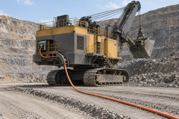
(N)TMCGEH3S cable is intended for mobile mining power connections exposed to repeated movement and abrasive ground contact. Its screened phases, separate earth conductors and ground-check core suit equipment layouts that require power supply and earth-continuity monitoring in one cable.
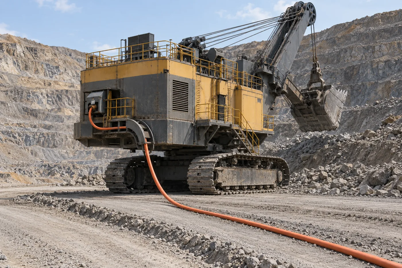
- Electric shovels and excavators: trailing supply between the distribution point and moving machine.
- Mining drills: mobile electrical feeds where the route and handling system accommodate the cable.
- Draglines, dredges and material-handling equipment: installations requiring flexible medium-voltage power and a pilot circuit.
Match the cable to the movement
Describe whether the cable trails along the ground, passes over guides or winds onto a powered reel. For reel-fed use, review drum geometry, tension, travel speed, reverse bending and the number of layers before accepting a construction. A trailing-cable designation alone does not establish a reeling speed or flex-cycle rating.
Keep the route clear of vehicle crossings and crushing points. Check connector size and pilot-circuit compatibility as well as voltage and phase cross-section. The ground-check conductor carries the monitoring circuit; the earth conductors provide the protective-earth path.
(N)TMCGEH3S specifications
The featured construction is the 6/10 kV, 3 × 120 + 2 × 50 + 1 × 16 mm² cable described above. The size-series data below are published reference-design values for preliminary comparison; confirm the final dimensions and operating limits on the agreed TEBAOFLEX quotation and drawing.
| Model | (N)TMCGEH3S |
|---|---|
| Rated voltage U₀/U (Um) | 6/10 (12) kV |
| Featured ordering designation | (N)TMCGEH3S 3 × 120 + 2 × 50 + 1 × 16 mm² |
| Core allocation | 3 phases + 2 earth conductors + 1 insulated ground-check conductor |
| Conductor / insulation / sheath | Class 5 tinned copper / EPR 3GI3 / orange TPU |
| Maximum conductor operating temperature | 90 °C |
| Individual metallic screen coverage | At least 60% |
| Pilot insulation | Reinforced thermoplastic elastomer, yellow |
Reference operating and test envelope
| Maximum short-circuit conductor temperature | 250 °C |
|---|---|
| Ambient temperature — fixed | −40 to +80 °C |
| Ambient temperature — fully flexible | −30 to +60 °C |
| Maximum tensile stress on power conductors | 15 N/mm² |
| Torsional stress reference | ±25°/m |
| Minimum bending radius | Determine for the installation duty according to DIN VDE 0298-3 and the approved cable design. |
| AC withstand test reference — power cores | 17 kV |
| AC withstand test reference — pilot/control core | 1 kV |
Reference dimensions, weight and electrical data
All configurations below use a 16 mm² pilot. Cross-sections are in mm². These values must be read as complete rows for their respective construction.
| Model + configuration (mm²) | Overall diameter (mm) | Approx. weight (kg/km) | Max. tensile force (N) | Max. phase DC resistance at 20 °C (Ω/km) | Reference current (A) |
|---|---|---|---|---|---|
| (N)TMCGEH3S 3 × 70 + 2 × 35 + 1 × 16 | 56.0–60.0 | 5 400 | 3 150 | 0.277 | 265 |
| (N)TMCGEH3S 3 × 95 + 2 × 50 + 1 × 16 | 56.8–60.8 | 6 500 | 4 275 | 0.210 | 319 |
| (N)TMCGEH3S 3 × 120 + 2 × 50 + 1 × 16 | 60.1–64.1 | 7 540 | 5 400 | 0.164 | 371 |
| (N)TMCGEH3S 3 × 185 + 2 × 70 + 1 × 16 | 69.6–73.6 | 10 150 | 8 325 | 0.108 | 488 |
Current-rating conditions: continuous operation, free in air at 30 °C ambient, three loaded cores, DC or 50–60 Hz AC. Apply the appropriate installation corrections; these figures are not wound-on-drum current ratings.
120 mm² reference-design detail
| Maximum phase-conductor diameter | 14.8 mm |
|---|---|
| Nominal operating capacitance | 0.63 µF/km |
| Nominal inductance | 0.26 mH/km |
Do not transfer diameter, weight or current values from a 10 mm² pilot version, LED variant or different jacket construction. Establish the required bend radius, pulling arrangement, connector entry and load current together before manufacture.
Standards
The following construction and test references support the specification of this (N)TMCGEH3S cable. State the required editions and inspection documentation in the purchase specification.
| Standard / method | Scope in the specification |
|---|---|
| DIN VDE 0250-813 | Construction reference for trailing cables; the model is based on this standard. |
| IEC 60228 | Class 5 flexible copper conductors and conductor-resistance requirements. |
| DIN VDE 0207 Part 20 | EPR insulation compound type 3GI3. |
| DIN VDE 0298-3 | Reference for installation-dependent cable bending requirements. |
| DIN VDE 0298-4 | Reference for current-carrying capacity and installation corrections. |
| IEC / EN 60332-1-2 | Single-cable vertical flame-propagation test reference for the documented reference design. |
| IEC / EN 60811-404 | Oil-immersion test reference for the documented reference sheath design. |
The official IEC 60228 scope explains the conductor sizes, wire requirements and resistance criteria covered by the standard.
Inspection information for the order
Specify the conductor-resistance results, power-core and pilot-core voltage tests, dimensional checks and sheath test records required for acceptance. Test voltage is separate from service voltage; agree the test duration and circuit connections in the inspection plan.
Related cable options
Compare these cable options by service combination, movement, load, voltage and transmission requirement.
(N)TMCGETMPU Cable 6/10 kV to 14/25 kV Reeling Mining Trailing Cable
A related cable option for a different application or duty profile.
View product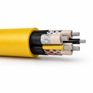
(N)TMCETMPU Cable 6/10 kV to 14/25 kV Portable Mining Trailing Cable
A related cable option for a different application or duty profile.
View product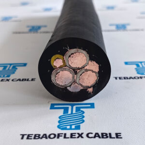
SHD-GC Cable 2kV-25kV Mining Power Cable
A related cable option for a different application or duty profile.
View productRequest a cable recommendation and quotation
Send the required services, cable length, mechanical duty, environment, termination and quantity. Our team will review the application before quoting.
- Include the product name or SKU plus the required cable length and quantity.
- Attach a specification, drawing or data sheet when available.