








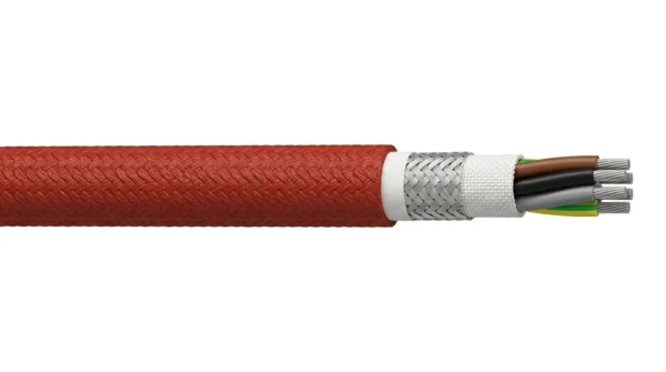




TF-PYRO-SM 0.6/1 kV Slag-Splash Protected Pyrojacketed EAF & Steel-Mill Power/Control Cable (+260 / +1,090 °C)
TF-PYRO-SM (TF-PYRO-SM-1KV) is an integral 0.6/1 kV molten-slag-splash and radiant-heat protected pyrojacketed power and control cable engineered for Electric Arc Furnaces (EAF), Ladle Furnaces (LF), BOF converters and continuous-casting tundish decks. Combining +260 °C PFA/mica-silicone cores, AISI 304 stainless wire braid armour and a vulcanized iron-oxide silicone-fiberglass outer pyrojacket, it sheds +1,090 °C molten splash without field sleeving.
TF-PYRO-SM 0.6/1 kV integral pyrojacketed slag-splash resistant power and control cables protect critical EAF, Ladle Furnace, BOF converter and continuous-casting circuits where +200 °C to +260 °C steady radiant heat coincides with flying +1,090 °C to +1,600 °C molten metal and slag splatter, spanning 2G1.5 mm² hydraulic proportional-valve cables up to 4G50 mm² melt-shop motor feeders.
Maintenance crews traditionally pull ordinary silicone or fluoropolymer cables through separate slip-on fiberglass fire sleeves—a slow, high-failure workaround that leaves air gaps, bunches at cable glands and lets molten slag burn straight through thin spots. TF-PYRO-SM unifies the entire thermal-armor stack on the factory extrusion line: 27 % nickel-plated Class 5 copper, 0.6/1 kV PFA or mica-silicone core insulation, optional EMC copper braid, multi-layer ceramic/E-glass thermal reflection tape, AISI 304 stainless-steel wire braid crush armour and a thick vulcanized iron-oxide red silicone-over-fiberglass outer pyrojacket.
When molten steel or slag strikes the smooth high-iron-oxide elastomer skin, droplets bead and roll off before heat penetrates the ceramic-glass barrier, achieving +260 °C continuous operation, +800 °C 20-minute radiant survival and +1,090 °C (2,000 °F) splash protection. Specify TF-PYRO-SM-C (EMC screened) for EAF electrode-mast proportional valves, oxy-fuel burner lances and slide-gate encoders, or TF-PYRO-SM-P for tundish cars and slag-raking drives; for secondary kA electrode-arm current, pair with TEBAOFLEX EAF Water-Cooled Cable. MOQ 50 m, 7 to 45 working days.
Explore the high-temperature wire and cable range for related configurations.
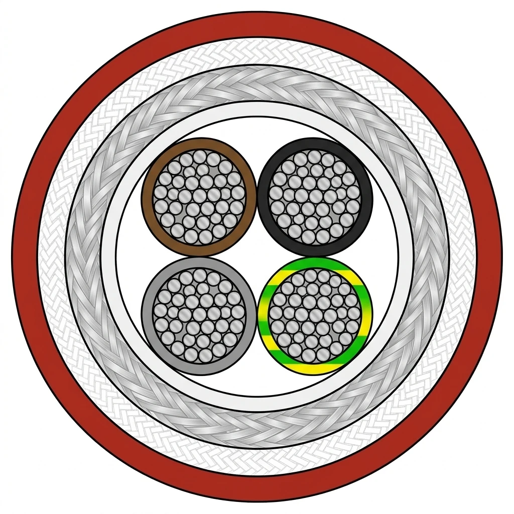
TF-PYRO-SM Integral Slag-Protected Thermal Armour
Multi-barrier metallurgical thermal-armour construction engineered to IEC 60502-1 0.6/1 kV dielectric testing and SAE AS1072 / UL 1441 pyrojacket thermal-splash principles.
| Component | Material and construction |
|---|---|
| 1. 27 % Nickel-Plated (or Silver-Plated) Class 5 Copper Conductors | IEC 60228 Class 5 fine-stranded nickel-clad copper resisting high-temperature annealing, vibration fatigue and oxidation up to +260 °C continuous. |
| 2. 0.6/1 kV PFA Fluoropolymer or Mica-Tape + Silicone Primary Insulation | Oil- and hydraulic-ester-impervious PFA cores (standard on valve/sensor builds) or phlogopite mica-tape + silicone fire-integrity cores (on emergency power builds). |
| 3. Ceramic-Glass Thermal Barrier, Optional EMC Screen & 304 SSWB Armour | Optional >= 80 % nickel/tinned-copper EMC braid (-C), wrapped with ceramic/alkali-free fiberglass heat-sink tapes and >= 80 % AISI 304 stainless-steel wire braid. |
| 4. Integral Vulcanized Iron-Oxide Silicone-Fiberglass Outer Pyrojacket | Heavy-wall braided/knitted E-glass sleeve integrally compounded with high-density iron-oxide fire-red silicone elastomer to shed molten metal and slag. |
TF-PYRO-SM Series & Sub-Model Breakdown
- TF-PYRO-SM: TEBAOFLEX integral pyrojacketed molten-slag-resistant steel-mill cable (0.6/1 kV)
- -C (Control / Pair): 27 % NPC + PFA cores + >= 80 % SPC EMC braid + 304 SSWB + iron-oxide silicone pyrojacket
- -P (Power Feeder): 27 % NPC + phlogopite mica + PFA/silicone + 304 SSWB + iron-oxide silicone pyrojacket
- -TC (Thermocouple): Type K / N / J / S thermocouple extension pairs under 304 SSWB and integral pyrojacket
- 304 SSWB: Internal AISI 304 austenitic stainless-steel wire braid mechanical crush and cut-through armour
TF-PYRO-SM EAF Mast, Oxygen Lance & Tundish Deck Duty
Purpose-built for steelmaking melt-shop, foundry pouring-deck, ferroalloy tapping-floor and aluminum casthouse splash zones.
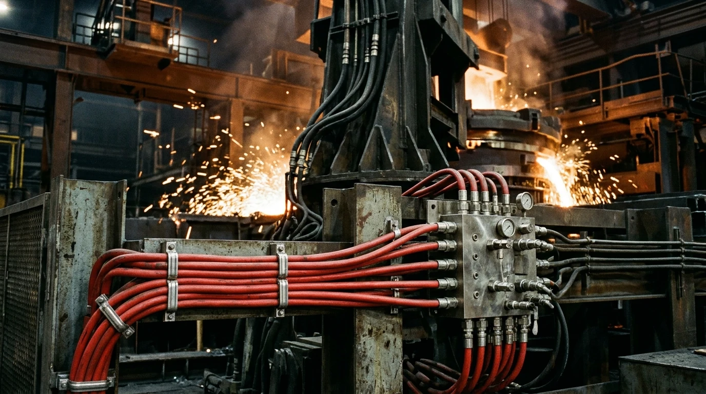
- Electric arc furnace (EAF) electrode-arm hydraulic proportional valves, roof-lift cylinders, supersonic oxygen/carbon lances and eccentric bottom tapping (EBT) gates.
- Ladle furnace (LF) wire-feeding machines, argon-stirring lance carriages, ladle turret slip-ring jumpers and ladle slide-gate hydraulic units.
- Continuous-casting tundish stopper-rod actuators, mould-level eddy-current sensors, torch-cutoff carriages and hot slab stamper/deburrer drives.
- Foundry cupola/induction pouring monorails, BOF converter sub-lance hoists, slag-pot skimmers and ferroalloy taphole mud-gun / drill rigs.
TF-PYRO-SM Pyrojacket vs YGC22 vs FEP-GSWB vs Water-Cooled
| Melt-Shop Cable Type | Circuit Role | Thermal & Slag Survival | Where Used on the Furnace |
|---|---|---|---|
| TF-PYRO-SM-C / -P (this page) | 0.6/1 kV multi-core power, valve & sensor | +260 °C continuous; sheds +1,090 °C molten slag splash | EAF mast valves, oxygen lances, EBT gates, tundish & torch-cutoff decks |
| YGC / YGCR / YGC22 | 0.6/1 kV multi-core power (1.5–185 mm²) | +180 °C ambient heat; not rated for direct molten slag | Perimeter furnace trays, blower rooms, kiln galleries & cable trenches |
| FEP/PFA-GSWB | 0.6/1 kV exposed steel-braid power | +260 °C chemical/oil proof; exposed braid traps slag beads | Pickling lines, hot hydraulic skids & dry radiant zones without slag pour |
| EAF Water-Cooled Cable | 5–45 kA secondary copper rope assembly | Active 4–6 bar internal water cooling + optional heat shield | Transformer delta closure to EAF / LF movable electrode arms |
Terminate TF-PYRO-SM using nickel-plated brass barrier/armour glands sized to clamp the internal 304 stainless braid while sealing over the red silicone pyrojacket.
TF-PYRO-SM Pyrojacketed Melt-Shop Cable RFQ Checklist
- Sub-series (TF-PYRO-SM-C screened control/pair, TF-PYRO-SM-P power feeder, or TF-PYRO-SM-TC thermocouple) and core × mm² layout.
- Furnace zone details: steady ambient temperature (°C), molten steel/slag splash exposure and fire-resistant hydraulic fluid type (water-glycol or phosphate ester).
- Whether IEC 60331-21 phlogopite mica fire-survival taping is required on emergency EBT / ladle-tilt circuits.
- Required total length and cut-drum breakdown (MOQ 50 m per specification, 7 to 45 working days).
Related selection resources
- Browse all Steel-Mill, EAF & High-Temperature Speciality Cables
- Pair with EAF Water-Cooled Secondary Furnace Cable (1,000–7,000 mm²)
- Compare YGC, YGCR & YGC22 +180 °C Metallurgical Silicone Power Cable
- Compare Ladle Transfer Car 0.6/1 kV Melt-Shop Drum Reeling Cable
- Compare FEP/PFA-GSWB & PFA-SSWB +260 °C Steel-Braided Power Cable
- Compare SIMH FE180 PH120 Fire-Survival Circuit-Integrity Cable
TF-PYRO-SM Pyrojacketed Slag-Resistant EAF Cable FAQ
Why use integral TF-PYRO-SM cable instead of pulling standard silicone cable through a loose fire sleeve?
Loose slip-on fire sleeves snag during pulling, leave air pockets that trap heat, and cannot seal cleanly inside cable glands—allowing hydraulic oil and conductive mill scale to wick inside; TF-PYRO-SM vulcanizes the iron-oxide silicone-fiberglass pyrojacket directly over a 304 stainless wire braid for a sealed, crush-proof single-piece cable.
What temperature and molten-splash exposure can TF-PYRO-SM withstand?
+260 °C continuous ambient operation, +800 °C short-term radiant exposure (15–20 minutes), and instantaneous shedding of +1,090 °C to +1,600 °C molten steel and slag droplets without sustaining flame.
Does TF-PYRO-SM resist fire-resistant EAF hydraulic fluids like water-glycol and phosphate esters?
Yes — while outer silicone sheds molten slag, the internal cores on TF-PYRO-SM-C use extruded PFA fluoropolymer insulation and inner bedding that remain chemically impervious to phosphate-ester, polyol-ester and water-glycol hydraulic fluids.
Can TF-PYRO-SM carry secondary kA current to EAF electrode arms?
No — TF-PYRO-SM is a 0.6/1 kV auxiliary power, hydraulic-valve and instrumentation cable (1.0 mm² to 50 mm²); for 5 kA to 45 kA transformer-to-electrode-arm secondary links, specify TEBAOFLEX EAF Water-Cooled Cable (1,000–7,000 mm²).
What is the minimum order quantity and manufacturing lead time for TF-PYRO-SM?
50 m per core/cross-section specification on export wooden drums, manufactured and 3,500 V AC tested in 7 to 45 working days.
TF-PYRO-SM-C Control & TF-PYRO-SM-P Power Schedule
TF-PYRO-SM 0.6/1 kV Voltage, +1,090 °C Splash & 304 Armour
- Sheds +1,090 °C molten slag splash: Heavy-build iron-oxide red silicone vulcanized over knitted E-glass sheds molten steel, slag globules and welding spatter up to +1,090 °C (+1,600 °C brief flash)
- +260 °C continuous core rating: Nickel-plated Class 5 copper with PFA fluoropolymer (or mica + silicone) primary insulation survives +260 °C continuous radiant heat beside furnace shells
- Internal 304 stainless wire braid: AISI 304 stainless-steel wire braid armour (SSWB) plus ceramic-glass thermal barrier tape prevents hot-scale cut-through, clamp crushing and hydraulic hose whip
- Eliminates manual fire-sleeve labor: Delivered as a factory-vulcanized single-piece drum cable from 2G1.5 mm² sensor/valve leads up to 4G50 mm² motor feeders—no snagging loose sleeves in glands
- 50 m melt-shop maintenance drums: Supplied in 50 m minimum order cut lengths with optional tinned/nickel copper EMC braid (-C) in 7 to 45 working days
| Parameter | Value |
|---|---|
| Rated voltage | 0.6/1 kV AC (600/1000 V) per IEC 60502-1 with 3500 V AC 5-minute routine dielectric withstand test |
| Core and cross-section range | Control and instrumentation 2G1.5 to 19G1.5 mm2 and 2x2x1.0 to 8x2x1.0 mm2; power feeders 3G2.5 to 4G50 mm2 |
| Thermal and splash ratings | -60 C to +260 C continuous ambient, +800 C 20-minute radiant exposure and +1090 C (2000 F) molten slag/steel splash shedding |
| Armour and bend radius | Internal AISI 304 stainless-steel wire braid (SSWB) beneath integral pyrojacket; minimum bend radius 10x OD fixed and 15x OD flexing |
| Minimum order and lead time | 50 m per specification on factory export drums, manufactured in 7 to 45 working days |
| Hydraulic fluid and slag resistance | PFA inner core system resists water-glycol and phosphate-ester fire-resistant EAF hydraulic fluids while outer pyrojacket sheds molten slag |
| Flame and halogen profile | Self-extinguishing per IEC 60332-1-2 / VW-1; mica-core emergency option maintains IEC 60331-21 circuit integrity |
TF-PYRO-SM-C Screened EAF Valve, Lance & Sensor Cable Schedule
| Model & Core / Pair Layout | Core Insulation | EMC Shield + Armour | Nom. OD (mm) | Continuous / Splash Rating | Approx. Weight (kg/km) | Drum MOQ | Next step |
|---|---|---|---|---|---|---|---|
| TF-PYRO-SM-C 2×2×1.0 mm² | PFA (+260 °C) | SPC Braid + 304 SSWB | 14.6 | +260 °C / +1,090 °C | 295 | 50 m | Request this size |
| TF-PYRO-SM-C 4×2×1.0 mm² | PFA (+260 °C) | SPC Braid + 304 SSWB | 17.4 | +260 °C / +1,090 °C | 415 | 50 m | Request this size |
| TF-PYRO-SM-C 3G1.5 mm² | PFA (+260 °C) | SPC Braid + 304 SSWB | 13.8 | +260 °C / +1,090 °C | 268 | 50 m | Request this size |
| TF-PYRO-SM-C 4G1.5 mm² | PFA (+260 °C) | SPC Braid + 304 SSWB | 14.8 | +260 °C / +1,090 °C | 312 | 50 m | Request this size |
| TF-PYRO-SM-C 5G1.5 mm² | PFA (+260 °C) | SPC Braid + 304 SSWB | 15.9 | +260 °C / +1,090 °C | 360 | 50 m | Request this size |
| TF-PYRO-SM-C 7G1.5 mm² | PFA (+260 °C) | SPC Braid + 304 SSWB | 17.2 | +260 °C / +1,090 °C | 435 | 50 m | Request this size |
| TF-PYRO-SM-C 12G1.5 mm² | PFA (+260 °C) | SPC Braid + 304 SSWB | 21.4 | +260 °C / +1,090 °C | 655 | 50 m | Request this size |
| TF-PYRO-SM-C 19G1.5 mm² | PFA (+260 °C) | SPC Braid + 304 SSWB | 24.8 | +260 °C / +1,090 °C | 910 | 50 m | Request this size |
| TF-PYRO-SM-C 4G2.5 mm² | PFA (+260 °C) | SPC Braid + 304 SSWB | 16.4 | +260 °C / +1,090 °C | 398 | 50 m | Request this size |
| TF-PYRO-SM-C 7G2.5 mm² | PFA (+260 °C) | SPC Braid + 304 SSWB | 19.2 | +260 °C / +1,090 °C | 565 | 50 m | Request this size |
TF-PYRO-SM-P 0.6/1 kV Melt-Shop & Tundish Power Feeder Schedule
| Model & Cross-Section | Core System | Armour + Outer Jacket | Nom. OD (mm) | Ref. Current at +180 °C Air (A) | Approx. Weight (kg/km) | Drum MOQ | Next step |
|---|---|---|---|---|---|---|---|
| TF-PYRO-SM-P 4G2.5 mm² | Mica + PFA/SiR | 304 SSWB + Pyrojacket | 15.8 | 24 | 375 | 50 m | Request this size |
| TF-PYRO-SM-P 4G4.0 mm² | Mica + PFA/SiR | 304 SSWB + Pyrojacket | 17.6 | 32 | 485 | 50 m | Request this size |
| TF-PYRO-SM-P 4G6.0 mm² | Mica + PFA/SiR | 304 SSWB + Pyrojacket | 19.4 | 42 | 615 | 50 m | Request this size |
| TF-PYRO-SM-P 4G10 mm² | Mica + PFA/SiR | 304 SSWB + Pyrojacket | 23.2 | 58 | 895 | 50 m | Request this size |
| TF-PYRO-SM-P 4G16 mm² | Mica + PFA/SiR | 304 SSWB + Pyrojacket | 26.4 | 78 | 1,240 | 50 m | Request this size |
| TF-PYRO-SM-P 4G25 mm² | Mica + PFA/SiR | 304 SSWB + Pyrojacket | 31.2 | 104 | 1,790 | 50 m | Request this size |
| TF-PYRO-SM-P 4G35 mm² | Mica + PFA/SiR | 304 SSWB + Pyrojacket | 34.8 | 128 | 2,310 | 50 m | Request this size |
| TF-PYRO-SM-P 4G50 mm² | Mica + PFA/SiR | 304 SSWB + Pyrojacket | 39.6 | 158 | 3,080 | 50 m | Request this size |
| TF-PYRO-SM-P 5G6.0 mm² | Mica + PFA/SiR | 304 SSWB + Pyrojacket | 21.2 | 42 | 735 | 50 m | Request this size |
| TF-PYRO-SM-P 5G16 mm² | Mica + PFA/SiR | 304 SSWB + Pyrojacket | 28.8 | 78 | 1,490 | 50 m | Request this size |
Thermocouple extension builds (TF-PYRO-SM-TC in Type K, N, J or S alloy pairs with individual + overall shield) are manufactured with the identical +1,090 °C outer pyrojacket upon request. Final OD and gland-sealing diameters are confirmed on the quotation drawing.
ASCII part references for BOM and ERP entry: TF-PYRO-SM-C-2X2X1.0, TF-PYRO-SM-C-4X2X1.0, TF-PYRO-SM-C-4G1.5, TF-PYRO-SM-C-7G1.5, TF-PYRO-SM-C-12G1.5, TF-PYRO-SM-P-4G6, TF-PYRO-SM-P-4G16, TF-PYRO-SM-P-4G25, TF-PYRO-SM-P-4G50.
TF-PYRO-SM Reference Standards (IEC 60502-1 & SAE AS1072)
| Standard or specification | Application |
|---|---|
| IEC 60502-1 & IEC 60331-21 Fire-Integrity Reference | 0.6/1 kV 3,500 V AC dielectric withstand and emergency fire-survival circuit integrity on mica-taped -P builds. |
| SAE AS1072 & UL 1441 Thermal-Splash Sleeve Principles | Iron-oxide silicone-coated heavy E-glass outer pyrojacket thermal resistance and molten-metal shedding design basis. |
| IEC 60228 Class 5 & ASTM B355 | Flexible nickel-plated copper conductor stranding for +260 °C thermal endurance. |
Certifications and document support
TEBAOFLEX ISO 9001 quality management and 3.5 kV melt-shop cable inspection
SAE AS1072 — High-temperature silicone-coated fiberglass fire-protection sleeve specification
IEC 60502-1 — Extruded power and control cables for 0.6/1 kV industrial circuits
Related cable options
Compare these cable options by service combination, movement, load, voltage and transmission requirement.
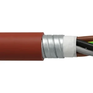
YGC, YGCR, YGCP & YGC22 0.6/1 kV Heavy-Duty Metallurgical Silicone Rubber Power Cable (-60 to +180 °C)
A related cable option for a different application or duty profile.
View product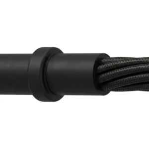
EAF & Ladle Furnace (LF) Water-Cooled Cable — 1,000–7,000 mm² Fluted-Core, Bumper & Swivel Secondary Leads
A related cable option for a different application or duty profile.
View product
Ladle Transfer Car & Steel Mill High-Temperature Reeling Cable (0.6/1 kV)
A related cable option for a different application or duty profile.
View productRequest a cable recommendation and quotation
Send the required services, cable length, mechanical duty, environment, termination and quantity. Our team will review the application before quoting.
- Include the product name or SKU plus the required cable length and quantity.
- Attach a specification, drawing or data sheet when available.