








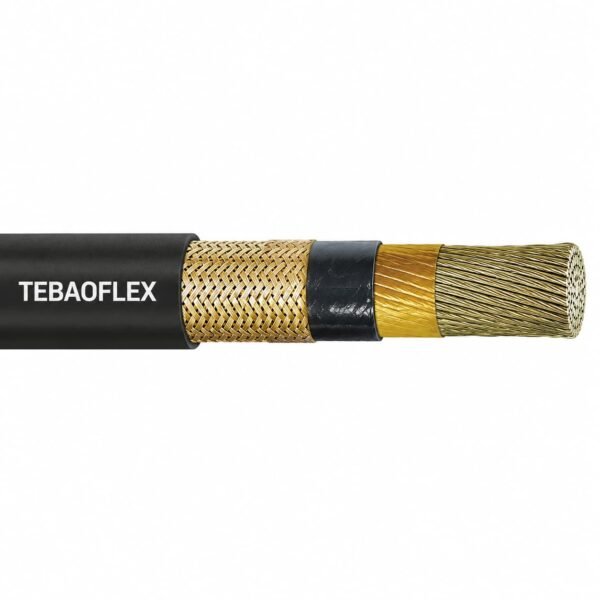
Type P 1C Armored & Sheathed 2 kV Power Cable
Type P 1C armored and sheathed cable is a 2,000 V AC single-conductor power cable for marine shipboard, fixed and floating offshore, land-based and oilfield facilities. Its irradiation-cross-linked polyolefin insulation is stated to resist oils, drilling muds and fluids, hydraulic gear oil, saltwater, abrasion, moisture and UV light.
- Voltage: 2,000 V AC
- Configuration: Type P 1C armored and sheathed cable
- Insulation: irradiated cross-linked polyolefin
- Mechanical protection: metallic braid armour with a non-metallic outer sheath
- Temperature: 125°C maximum insulation operating temperature; 110°C continuous rating stated for UL, CSA and ABS
- Ampacity basis: free air or raceway at 45°C ambient, using the applicable stated temperature column
For a technical quotation, provide conductor size, route, ambient conditions, termination method and required project documentation.
Type P 1C armored and sheathed cable for 2 kV marine and offshore power
Type P 1C armored and sheathed cable is intended for 2,000 V AC electrical power service on shipboard and fixed or floating facilities, marine vessels, land-based facilities and oilfield equipment. This single-conductor Type P construction combines irradiation-cross-linked polyolefin insulation with metallic braid armour and a protective outer sheath. The supplied material connects the insulation system with resistance to oils, drilling muds and fluids, hydraulic gear oil, saltwater, abrasion, moisture and UV light.
Select Type P 1C armored and sheathed cable where the cable schedule requires a one-core Type P power circuit and route conditions call for an armoured, sheathed construction. The stated 125°C maximum insulation operating temperature is different from the supplied 110°C continuous rating; use the designated ampacity column and the real installation condition rather than selecting solely by insulation temperature.
- Suitable for: stated 2 kV AC marine, offshore, oilfield and facility power routes.
- Confirm before ordering: conductor size, installation method, ambient temperature, ampacity basis, armour bonding, glands and required documents.
- Choose another construction when: the project requires a different voltage class, a multi-core cable or a defined special-duty construction.
Review the Oil and Gas Cables range and the Marine & Offshore Cable Solutions page for related selection paths. Detailed Type P 1C armored and sheathed cable data is in the technical tabs.
Type P 1C armored and sheathed cable construction
Type P 1C armored and sheathed cable uses a single insulated conductor, metallic braid armour and a non-metallic outer sheath. The supplied product image visibly shows the braid and black sheathing around the insulated conductor. The supplied Type P family reference identifies bronze braid as the standard armour material and tinned-copper braid as an option; confirm the ordered armour material on the final drawing.
| Conductor configuration | Single conductor (1C) |
|---|---|
| Insulation | Irradiated cross-linked polyolefin |
| Armour | Metallic basket-weave braid; confirm ordered material |
| Outer sheath | Non-metallic outer sheath; black sheath visible in supplied product image |
| Insulation temperature reference | 125°C maximum operating temperature |
Construction selection notes
- Type P 1C armored and sheathed cable adds mechanical protection to the single-conductor Type P route; it is not a replacement for a different voltage, core configuration or project-specific screen design.
- Confirm the armour material, electrical continuity/bonding requirements, cable gland, termination and route support before release.
- The supplied source does not state final insulation thickness, bend radius or conductor stranding for each size. Obtain the approved dimensional drawing for the ordered Type P 1C armored and sheathed cable size.
Type P 1C armored and sheathed cable applications
Type P 1C armored and sheathed cable is specified for 2,000 V AC service on marine vessels, offshore fixed and floating facilities, land-based facilities and oilfield equipment. Its stated resistance to drilling fluids, hydraulic gear oil, saltwater, abrasion, moisture and UV exposure supports selection for demanding routes, provided the complete installation is checked against the project specification.

Installation and selection guidance
- Use Type P 1C armored and sheathed cable for the specified single-conductor power circuit, not as a generic replacement for a multi-core, unarmoured or medium-voltage cable.
- Base Type P 1C armored and sheathed cable ampacity on the selected free-air or raceway condition, 45°C ambient basis and stated temperature column.
- Confirm the location, support method, armour bonding, route protection, bending arrangement and termination system before ordering.
- For marine and offshore projects, specify the governing project standard, classification documentation and inspection requirements in the RFQ.
Type P 1C armored and sheathed cable gives procurement teams a separate path when a single-core Type P power feeder needs armour and sheath protection instead of the existing route-protected unarmoured construction.
Type P 1C armored and sheathed cable specifications
| Rated voltage | 2,000 V AC |
|---|---|
| Maximum insulation operating temperature | 125°C |
| Continuous operating temperature | 110°C, stated for UL, CSA and ABS |
| Emergency overload | 30 minutes followed by a 1½-hour cooling period |
| Ampacity basis | Free air or raceway, 45°C ambient; use the selected stated temperature column |
Nominal dimensions and weight
Type P 1C armored and sheathed cable dimensions are nominal, subject to normal manufacturing tolerances and may change without notice. Confirm the exact product number and approved drawing before ordering.
| Conductor size | Nominal conductor diameter (in) | Nominal conductor diameter (mm) | Nominal overall diameter (in) | Nominal overall diameter (mm) | Nominal weight (lb/1,000 ft) | Nominal weight (kg/km) |
|---|---|---|---|---|---|---|
| 8 AWG | .252 | 6.41 | .440 | 11.2 | 173 | 258 |
| 6 AWG | .304 | 7.73 | .492 | 12.5 | 230 | 343 |
| 4 AWG | .354 | 9.00 | .562 | 14.3 | 302 | 449 |
| 3 AWG | .376 | 9.55 | .584 | 14.8 | 331 | 493 |
| 2 AWG | .401 | 10.19 | .609 | 15.5 | 366 | 545 |
| 1 AWG | .431 | 10.95 | .630 | 16.0 | 413 | 615 |
| 1/0 AWG | .522 | 13.26 | .730 | 18.5 | 572 | 851 |
| 2/0 AWG | .568 | 14.42 | .770 | 19.6 | 658 | 979 |
| 3/0 AWG | .577 | 14.66 | .785 | 19.9 | 711 | 1 058 |
| 4/0 AWG | .682 | 17.33 | .930 | 23.6 | 995 | 1 480 |
| 250 MCM | .707 | 17.96 | .955 | 24.2 | 1 097 | 1 633 |
| 300 MCM | .785 | 19.95 | 1.043 | 26.5 | 1 294 | 1 926 |
| 350 MCM | .853 | 21.67 | 1.111 | 28.2 | 1 503 | 2 236 |
| 400 MCM | .908 | 23.07 | 1.166 | 29.6 | 1 723 | 2 565 |
| 500 MCM | .978 | 24.85 | 1.236 | 31.4 | 1 998 | 2 973 |
| 600 MCM | 1.085 | 27.56 | 1.343 | 34.1 | 2 375 | 3 534 |
| 700 MCM | 1.160 | 29.46 | 1.418 | 36.0 | 2 637 | 3 925 |
| 750 MCM | 1.177 | 29.90 | 1.435 | 36.4 | 2 759 | 4 106 |
| 777 MCM | 1.260 | 32.00 | 1.518 | 38.5 | 3 237 | 4 817 |
| 1111 MCM | 1.517 | 38.54 | 1.785 | 45.5 | 4 362 | 6 491 |
Ampacity at 45°C ambient in free air
| Conductor size | IEEE 45.8 Type P 100°C (A) | IEC* 110°C (A) | Recommended 95°C (A) | Recommended 110°C (A) | Recommended 125°C (A) |
|---|---|---|---|---|---|
| 8 AWG | 72 | 77 | 63 | 82 | 90 |
| 6 AWG | 96 | 103 | 88 | 116 | 126 |
| 4 AWG | 109 | 117 | 111 | 145 | 158 |
| 3 AWG | 128 | 137 | 116 | 160 | 176 |
| 2 AWG | 146 | 156 | 135 | 178 | 195 |
| 1 AWG | 169 | 181 | 146 | 199 | 217 |
| 1/0 AWG | 194 | 208 | 195 | 257 | 281 |
| 2/0 AWG | 227 | 243 | 220 | 292 | 319 |
| 3/0 AWG | 262 | 281 | 235 | 324 | 354 |
| 4/0 AWG | 300 | 321 | 302 | 399 | 437 |
| 250 MCM | 351 | 376 | 328 | 453 | 495 |
| 300 MCM | 407 | 436 | 363 | 503 | 550 |
| 350 MCM | 455 | 487 | 407 | 564 | 617 |
| 400 MCM | 516 | 553 | 454 | 631 | 692 |
| 500 MCM | 588 | 630 | 509 | 706 | 772 |
| 600 MCM | 630 | 675 | 570 | 795 | 871 |
| 700 MCM | 678 | 726 | 609 | 851 | 932 |
| 750 MCM | 731 | 783 | 637 | 895 | 979 |
| 777 MCM | 822 | 881 | 717 | 1 006 | 1 101 |
| 1111 MCM | 1 025 | 1 098 | 896 | 1 255 | 1 374 |
- IEC* ampacity values are prorated from square-millimetre sizes from IEC 60092-352 and DNV-OS-D201, as stated in the supplied data.
- Apply the Type P 1C armored and sheathed cable ampacity only to the selected installation condition and temperature column.
- Do not use these nominal values as a substitute for the ordered cable drawing, protection study or termination review.
Type P 1C armored and sheathed cable standards and references
The supplied Type P 1C armored and sheathed cable information states a 110°C continuous operating rating for UL, CSA and ABS. The following references are presented with the relationship supported by the supplied data and the Type P family reference; confirm the required current edition and model-specific documentation before ordering.
| Type P marine/offshore reference | IEEE 45.8 and IEEE 1580 |
|---|---|
| UL marine shipboard reference | UL 1309, Type X110 insulation reference |
| CSA marine cable reference | CSA C22.2 No. 245 |
| Ampacity calculation references | IEC 60092-352 and DNV-OS-D201 for the stated prorated IEC values |
| Temperature reference | 110°C continuous operation stated for UL, CSA and ABS |
Documentation to identify at RFQ
- State the required project standard edition, vessel/offshore classification, inspection record and test documentation for the Type P 1C armored and sheathed cable order.
- Confirm whether armour continuity or bonding details are required at terminations; the metallic armour is not automatically the complete equipment grounding path.
- Provide the required fire, hazardous-location, cold-environment and material-resistance documentation only when it is specified for the project and ordered construction.
Related cable options
Compare these cable options by service combination, movement, load, voltage and transmission requirement.
Type P 1C Unarmoured 2 kV Marine Power Cable
A related cable option for a different application or duty profile.
View product
Type P VFD Cable 2000V 1/0 AWG to 777 MCM Unarmored
A related cable option for a different application or duty profile.
View product
Type P Control Cable 600V / 0.6/1kV 18 AWG Armored and Sheathed
A related cable option for a different application or duty profile.
View productRequest a cable recommendation and quotation
Send the required services, cable length, mechanical duty, environment, termination and quantity. Our team will review the application before quoting.
- Include the product name or SKU plus the required cable length and quantity.
- Attach a specification, drawing or data sheet when available.