

Project record · Poland · Open-pit mine · Bucket-wheel excavator
Bucket-Wheel Excavator Reeling Cable for a Polish Mine: 12/20 kV (N)TSCGECEWÖU with a Witnessed Factory Test
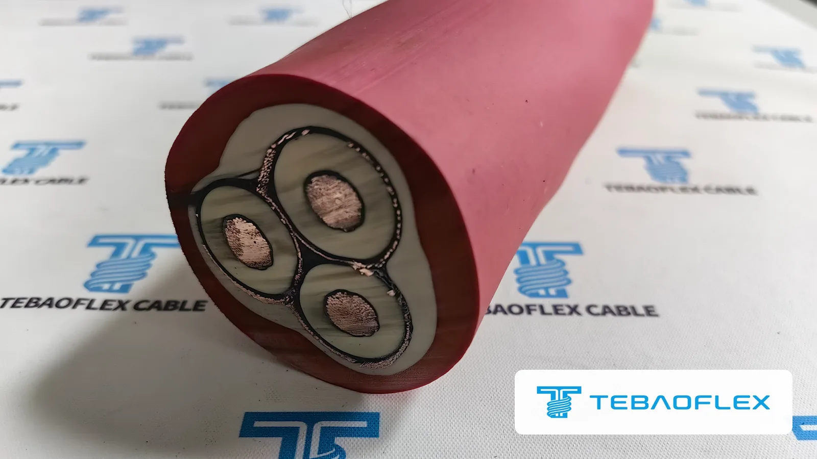
A Polish mining company needed bucket wheel excavator reeling cable: a 12/20 kV supply that is wound on the excavator's motorised cable reel and connects the machine to the mine transformer. TEBAOFLEX made two drums, 500 m and 480 m, of (N)TSCGECEWÖU 12/20 kV 3×35+3×25/3 with tinned copper conductors, EPR insulation, an individual tinned copper wire screen on each core and a red rubber outer sheath. On 27 September 2026 the buyer's QC inspector witnessed the factory acceptance test at our factory: 29 kV AC for 5 minutes without breakdown, partial discharge of 2.0 pC against a 10 pC limit, and a conductor resistance of 0.529 Ω/km. Both drums then shipped.
Project at a glance
| Location | Poland, open-pit mine |
|---|---|
| End user | A Polish mining company (name not published). The same buyer ordered the low-voltage reeling cable described in the stacker-reclaimer reeling cable case. |
| Machine | Bucket-wheel excavator with a motorised cable reel |
| Cable duty | 12/20 kV power supply wound on the excavator's cable reel and connected to the mine transformer |
| Cable | (N)TSCGECEWÖU 12/20 kV 3×35+3×25/3 (written (N)TSCGECEWOEU in the factory acceptance test report), red outer sheath; construction with reference to DIN VDE 0250-813, the standard the buyer specified |
| Quantity | Two drums: 500 m and 480 m |
| Overall diameter | 60.57 mm measured (nominal 60 mm, maximum 63 mm in the test report) |
| Factory acceptance test | 27 September 2026 at the TEBAOFLEX factory, witnessed by the buyer's QC inspector |
| Key results | 29 kV AC for 5 minutes without breakdown; partial discharge 2.0 pC (limit 10 pC); conductor resistance 0.529 Ω/km (limit 0.565 Ω/km) |
| Documents | Factory acceptance test report with measured values; the buyer also asked for a Declaration of Conformity with the delivery documents |
| Status | Both drums shipped |
What reeling cable does a bucket-wheel excavator need?
A bucket-wheel excavator reeling cable is a flexible, screened medium-voltage rubber cable that is wound on and off the excavator's motorised cable reel. The machine travels along the mine bench on crawlers, so the cable that feeds it from the mine transformer is paid out and reeled in whenever the machine travels, under tension, bending and torsion, in mud, frost and sun. For this Polish mine the buyer specified (N)TSCGECEWÖU 12/20 kV 3×35+3×25/3, a construction with reference to DIN VDE 0250-813.
- Bucket wheel and boom: the wheel digs material onto the boom conveyor
- Superstructure with the drives, switchgear and operator cab
- Crawler travel gear: the machine moves along the mine bench
- Motorised cable reel on the excavator
- The (N)TSCGECEWÖU 12/20 kV reeling cable, paid out and wound back as the excavator travels
- Mine transformer or switching point that feeds the cable
At 12/20 kV the cable has to control the electric field as well as survive the reel. Each power core therefore has a semi-conductive layer on both sides of its EPR insulation and an earthed tinned copper wire screen around it, inside rubber sheaths that keep the core assembly round and flexible. The letters of a designation like this one are explained, as far as the VDE legend defines them, in our guide to reading VDE cable designations. The same designation is also built as a submersible pump cable with separate earth cores and a black 5GM3 sheath, described on the (N)TSCGECEWÖU submersible cable page.
(N)TSCGECEWOEU 12/20 kV 3×35+3×25/3: construction and measured dimensions
The (N)TSCGECEWÖU 12/20 kV cable of this order has three 35 mm² Class 5 tinned copper power cores, each with semi-conductive conductor and insulation screens, 3GI3-type EPR insulation and its own tinned copper wire screen; the three screens form the 25 mm² protective conductor. A GM1b inner sheath and a red 5GM5 outer sheath complete it. The factory acceptance test measured 5.5 mm of insulation on each core and an overall diameter of 60.57 mm.
| Layer | Specification (test report) | Measured at the factory acceptance test |
|---|---|---|
| Power conductors | 3 × 35 mm², Class 5 flexible tinned copper, DIN VDE 0295 / IEC 60228 | Conforms (visual check and material certificate) |
| Conductor screen | Semi-conductive rubber screening compound | 0.5 mm |
| Insulation | 3GI3-type EPR, natural colour; nominal 5.5 mm, minimum 4.95 mm | 5.5 mm on cores 1, 2 and 3 |
| Insulation screen | Semi-conductive rubber screening compound | 0.5 mm |
| Tape over insulation screen | Semi-conductive nylon tape | Conforms (visual check) |
| Individual screens / protective conductor | Tinned copper wire screen on each core, 3 × 25/3 mm² | Conforms |
| Tape over the metallic screens | Semi-conductive tape | Conforms (visual check) |
| Inner sheath | GM1b-type EPR compound, natural colour | — |
| Outer sheath | 5GM5-type rubber compound, red; nominal 4.0 mm, minimum 3.4 mm | 4.31 mm |
| Overall diameter | Nominal 60 mm, maximum 63 mm | 60.57 mm |
| Core identification | Cores numbered 1, 2, 3 | Not a test report item |
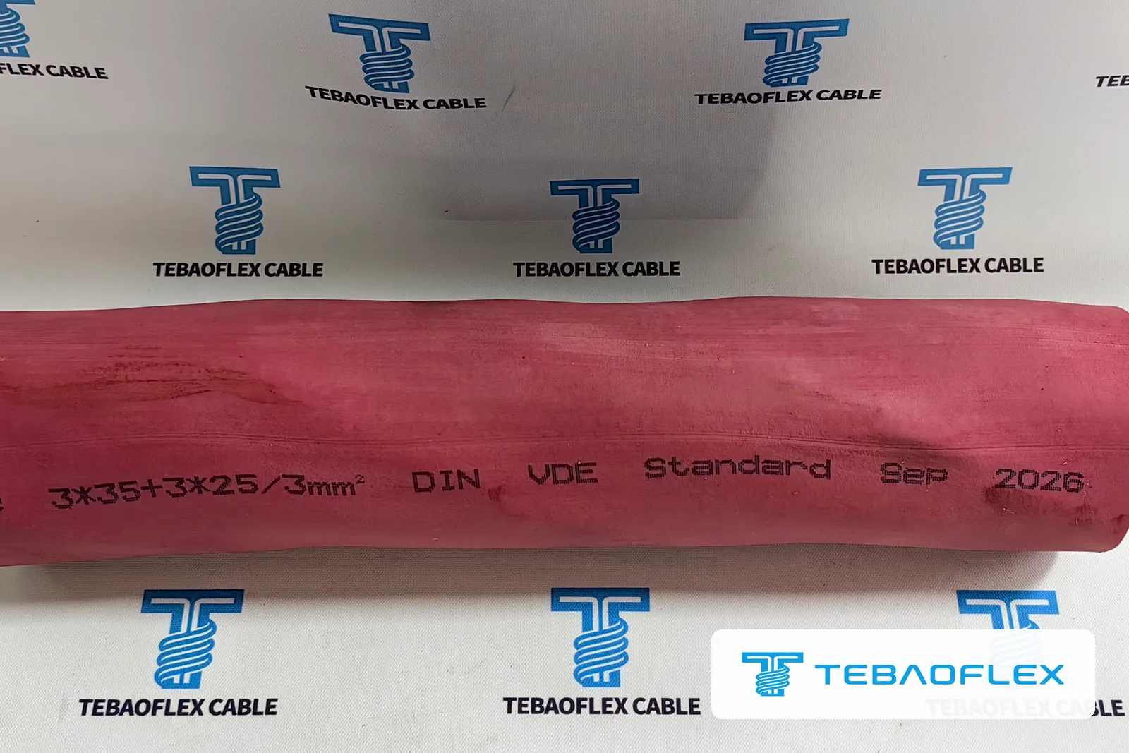
| Sheath print | Inkjet, clear and complete | Pass (part of the legend: “… 3*35+3*25/3mm² DIN VDE Standard Sep 2026”) |
Specification values are those in the factory acceptance test report for this order, except the conductor class and the 3GI3 insulation grade, which come from the order's construction sheet. Why flexible reeling cables use EPR rather than XLPE insulation is explained in our EPR insulation guide.
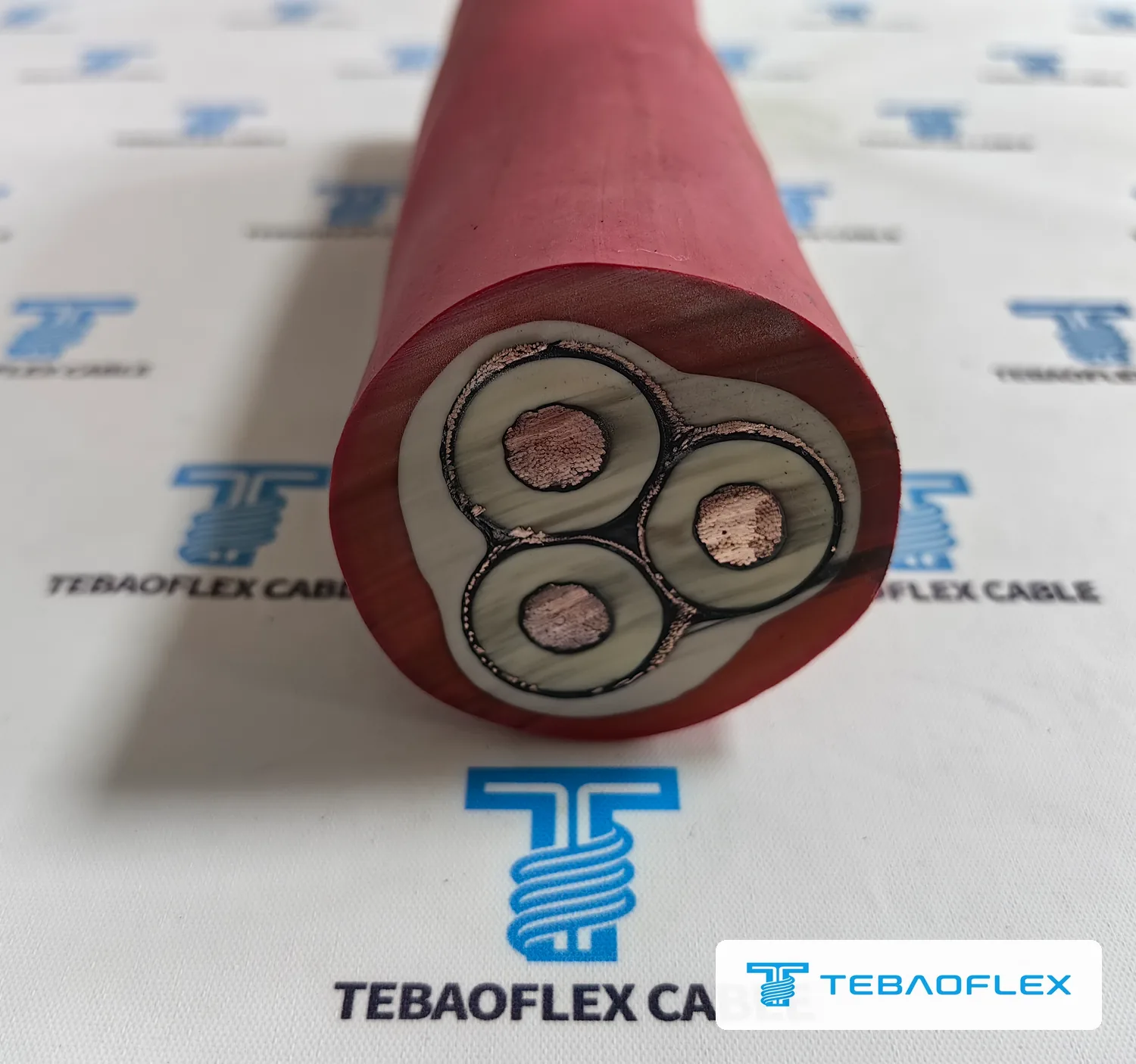
- Power conductor: Class 5 flexible tinned copper, DIN VDE 0295 / IEC 60228, 35 mm²
- Conductor screen: semi-conductive rubber, 0.5 mm
- Insulation: 3GI3-type EPR, nominal 5.5 mm
- Insulation screen: semi-conductive rubber, 0.5 mm, with semi-conductive nylon tape over it
- Individual tinned copper wire screen on each core; the three screens together are the 25 mm² protective conductor (3×25/3)
- Central rubber filler
- Inner sheath: GM1b-type EPR compound
- Outer sheath: 5GM5-type rubber compound, red, nominal 4.0 mm
What does 3×35+3×25/3 mean on this medium-voltage reeling cable?
The marking 3×35+3×25/3 means three 35 mm² power cores plus a 25 mm² protective conductor divided into three equal parts. In this (N)TSCGECEWÖU cable each part is the tinned copper wire screen around one power core, so the cable has no separate earth cores: every core carries its own earthed screen, and the three screens together are the protective conductor.
That arrangement matters at 12/20 kV. Each power core is enclosed by its own earthed wire screen, so the electric field stays inside that core's insulation and an insulation fault goes straight to earth through the screen around it. The protective conductor is shared equally by the three cores, and the inner sheath fills the gaps between them to give the round, solid core assembly a reel needs. For comparison, the low-voltage reeling cable the same buyer ordered carries its protective conductor as three separate green-yellow cores in the outer gaps, as described in the (N)SHTÖU-J stacker-reclaimer case record.
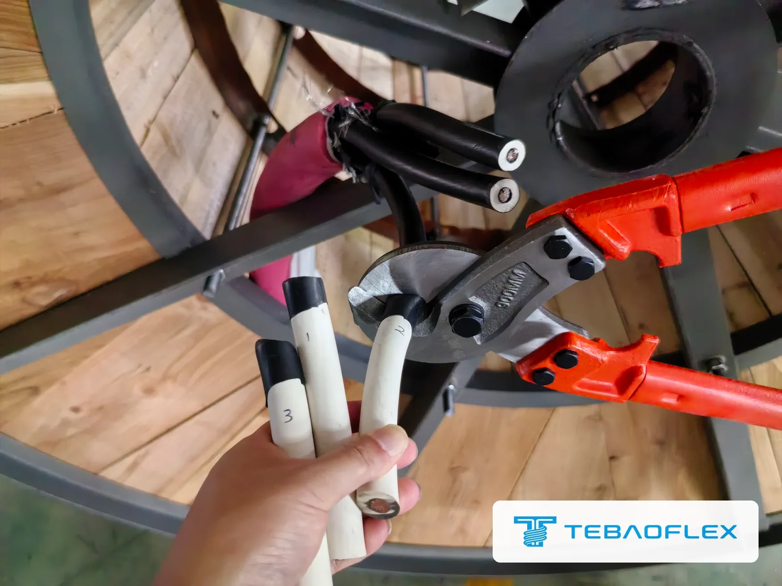
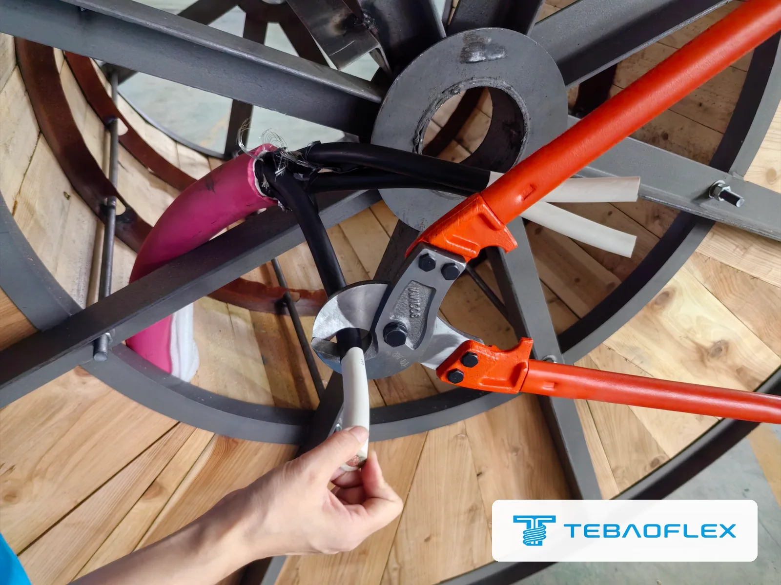
How are the three medium-voltage power cores identified at the excavator and the transformer?
Each 35 mm² power core of the (N)TSCGECEWÖU 12/20 kV cable in this Polish bucket-wheel excavator order is numbered 1, 2 or 3 on its insulation. The buyer asked how the installer would tell the cores apart when connecting the excavator and the transformer; the numbers let each core be matched to the same phase at both ends without tracing it through the cable.
12/20 kV cable factory acceptance test: 29 kV voltage test, partial discharge, resistance and dimensions
The factory acceptance test report for this (N)TSCGECEWÖU 12/20 kV order covers both drums, 500 m and 480 m, with one set of results: an AC voltage test at 29 kV for 5 minutes without breakdown, a partial discharge measurement of 2.0 pC against a 10 pC limit, conductor resistance of 0.529 Ω/km against the 0.565 Ω/km limit, insulation resistance, continuity, layer thicknesses, overall diameter, printing and drum length. The buyer's QC inspector witnessed the tests on 27 September 2026.
| Test | Requirement (test report) | Result |
|---|---|---|
| AC voltage test, resonant test set | 29 kV AC for 5 minutes, no breakdown | No breakdown |
| Partial discharge, series resonance PD system in a shielded test room | ≤ 10 pC | 2.0 pC |
| Conductor DC resistance, 35 mm² | ≤ 0.565 Ω/km at 20 °C (IEC 60228, Class 5, tinned copper) | 0.529 Ω/km |
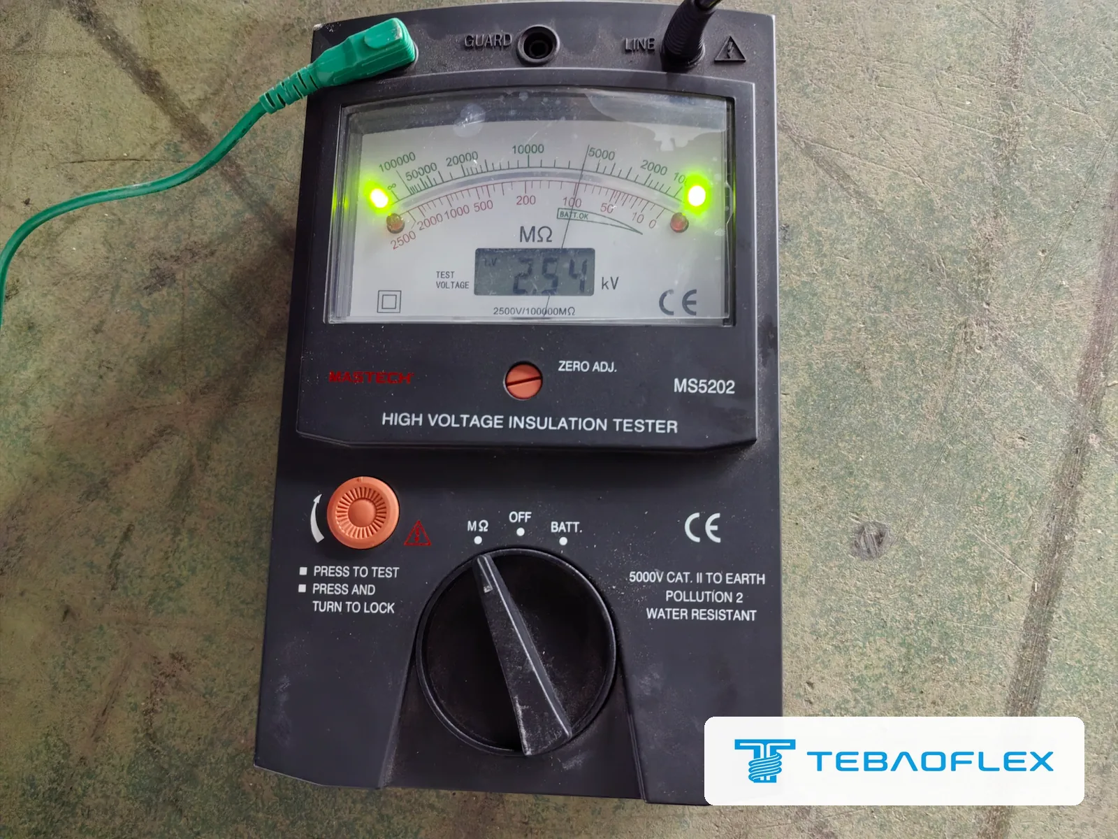
| Insulation resistance | ≥ 20 MΩ·km | Needle at about 5,000 MΩ at 2.5 kV DC |
| Continuity | Each power core continuous | Pass |
| Insulation thickness | Nominal 5.5 mm, minimum 4.95 mm | 5.5 mm on each core |
| Conductor and insulation screens | Semi-conductive | 0.5 mm each |
| Outer sheath thickness | Nominal 4.0 mm, minimum 3.4 mm | 4.31 mm |
| Overall diameter | Nominal 60 mm, maximum 63 mm | 60.57 mm |
| Printing | Inkjet, clear and complete | Pass |
| Drum length | 500 m per drum, checked by the meter marking on the sheath | 500 m and 480 m (one drum shortened by 20 m, see below) |
AC voltage test: 29 kV for 5 minutes
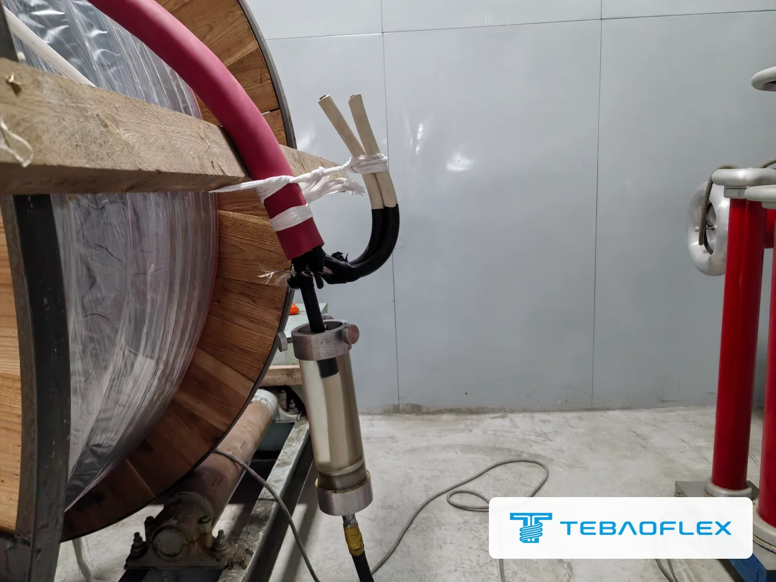
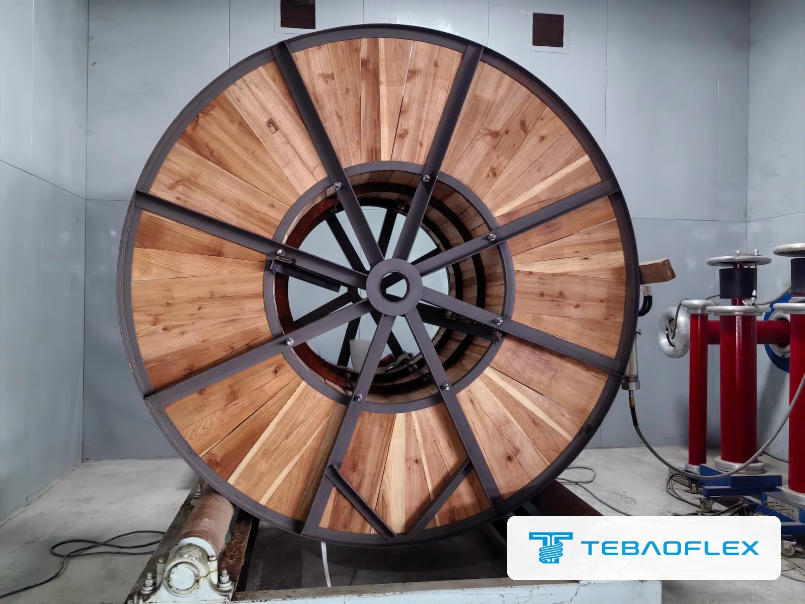
The cable was connected to a resonant test set and held at 29 kV AC for 5 minutes, the test voltage set in the report for this 12/20 kV order. There was no breakdown. A breakdown would show a weak point anywhere in the insulation of the full drum length.
Insulation resistance and continuity
The insulation tester applies a DC test voltage, shown on its digital display (2.54 kV here); the resistance is read on the analogue scale, where the needle stood at about 5,000 MΩ. Insulation resistance per kilometre is the reading multiplied by the length in kilometres, so a 5,000 MΩ reading meets the report's 20 MΩ·km minimum on any length above 4 m. Continuity was checked on each power core at the drum ends.
Dimensions: insulation, screens and overall diameter
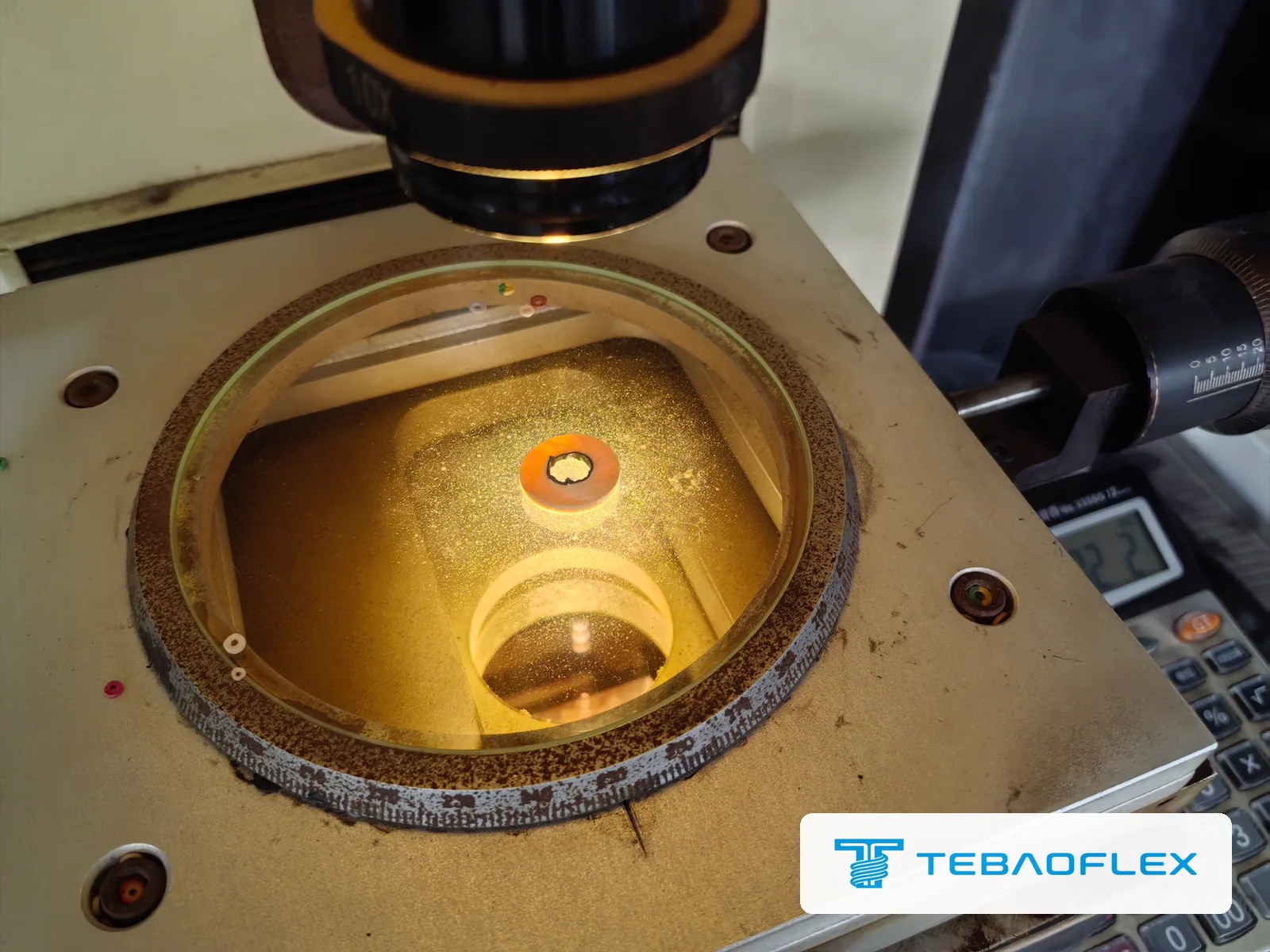
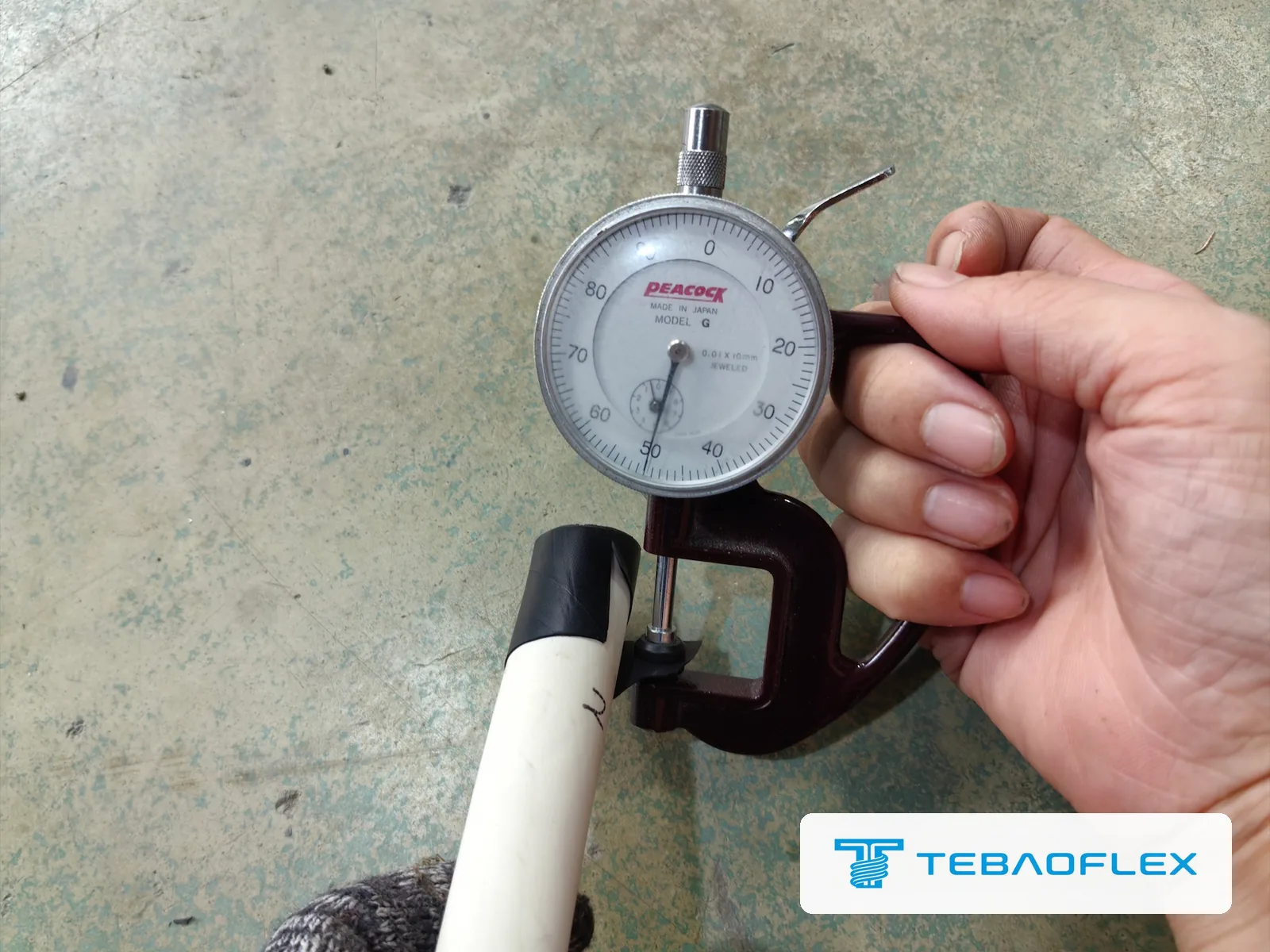
Slices cut from the drum end were measured for insulation, screen and sheath thickness; the photographs show an insulation slice on the measuring projector and a dial thickness gauge on the insulation screen, and the report lists micrometer and caliper readings. The insulation measured 5.5 mm on each core, both semi-conductive screens 0.5 mm, the outer sheath 4.31 mm and the overall diameter 60.57 mm.
Partial discharge test on a medium-voltage reeling cable: what 2.0 pC means
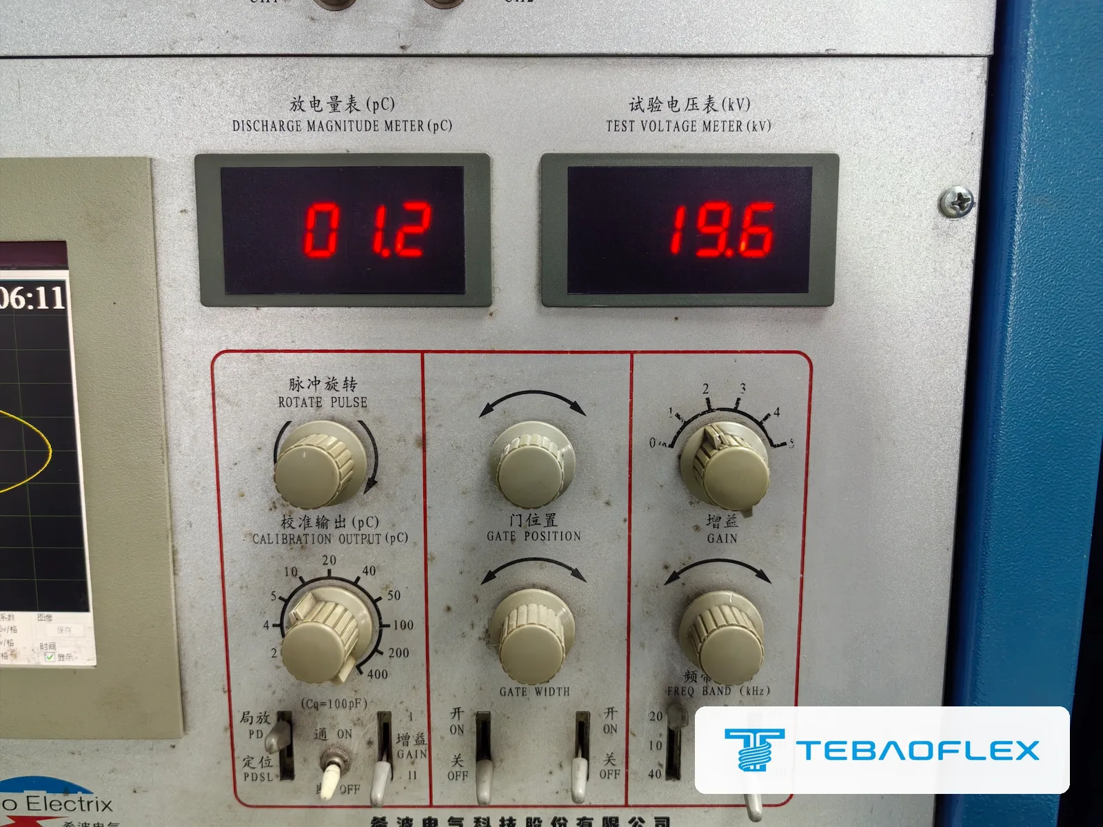
Partial discharge is a localised electrical discharge that only partly bridges the insulation, typically in a gas-filled void, at a contaminant or protrusion, or at a gap between the insulation and a semi-conductive screen. Measured as apparent charge in picocoulombs (pC), it reveals defects that can pass a voltage withstand test but erode the insulation over years. The 12/20 kV cable of this order measured 2.0 pC against the 10 pC limit in its factory acceptance test report.
The measurement was made in a shielded test room, which keeps outside electrical noise out of a reading of a few picocoulombs. The photograph is a snapshot of the panel taken during the test, with 1.2 pC on the discharge meter and 19.6 kV on the voltage meter; the result entered in the report is 2.0 pC.
What should a factory test report for a medium-voltage reeling cable include?
A factory test report for a medium-voltage reeling cable should give measured values beside each requirement, not only pass/fail. The Polish buyer of this 12/20 kV cable asked for the tests on each drum, conductor and protective-conductor resistance corrected to 20 °C, the voltage test result, insulation resistance, the verified dimensions, and partial discharge and screen inspection results, sent for acceptance before shipment, with a Declaration of Conformity in the delivery documents.
- Every drum or production length covered, with the lengths stated, so the buyer can see which drums the readings apply to.
- Measured values beside each requirement: conductor and protective-conductor resistance corrected to 20 °C, the test voltage and duration, insulation resistance, partial discharge level, layer thicknesses and overall diameter.
- Screen inspection for medium-voltage cables: semi-conductive screens and the metallic screen or braid checked for continuity and construction.
- Test methods and equipment, so the buyer can see how each value was obtained.
- The report before shipment, for verification and acceptance, and a Declaration of Conformity with the delivery documents.
This order's report covers both drums, 500 m and 480 m, in one table: it gives measured values for the semi-conductive screens, insulation, outer sheath, overall diameter, insulation resistance, conductor resistance and partial discharge, and pass results for the other items, including the AC voltage test, continuity, printing and length.
The buyer had first received a template showing the planned tests. It did not list every item their requirements covered, and the buyer asked for the full range. TEBAOFLEX marked the key tests on that template in yellow so the buyer could check that their requirements were covered, and sent the final report with the measured values after the witnessed test. Which standard, edition and acceptance records to name in a medium-voltage mining cable enquiry is covered in step 7 of our medium-voltage mining cable selection guide.
Witnessed FAT: what the buyer's QC inspector saw at the factory
On 27 September 2026 the buyer's QC inspector visited the TEBAOFLEX factory and witnessed the factory acceptance test of the (N)TSCGECEWÖU 12/20 kV drums: the AC voltage and partial discharge tests in the shielded test room, the insulation resistance and continuity checks, sample cutting, thickness measurements, and the strip checks of the conductor and screens.

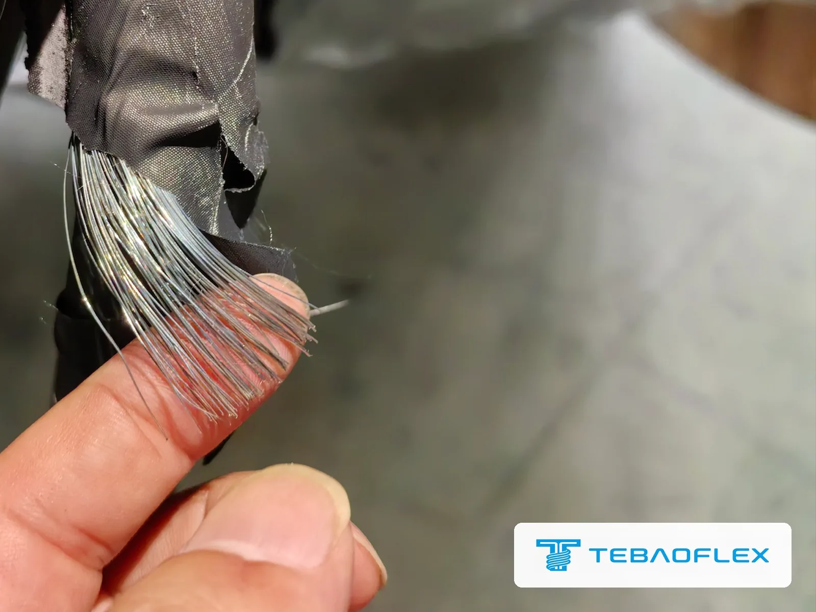
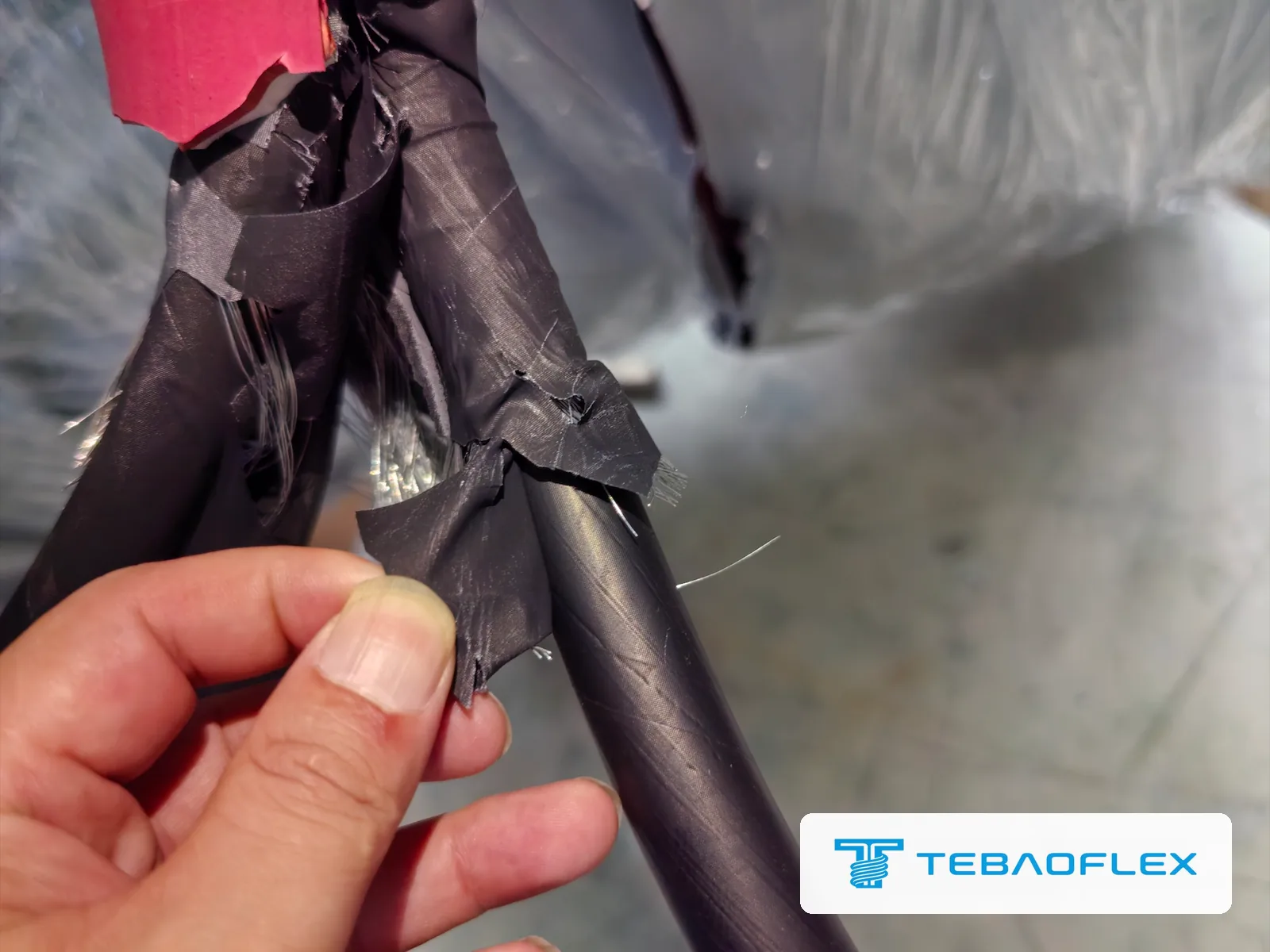
How do you check that the conductor and the screen wires are tinned copper?
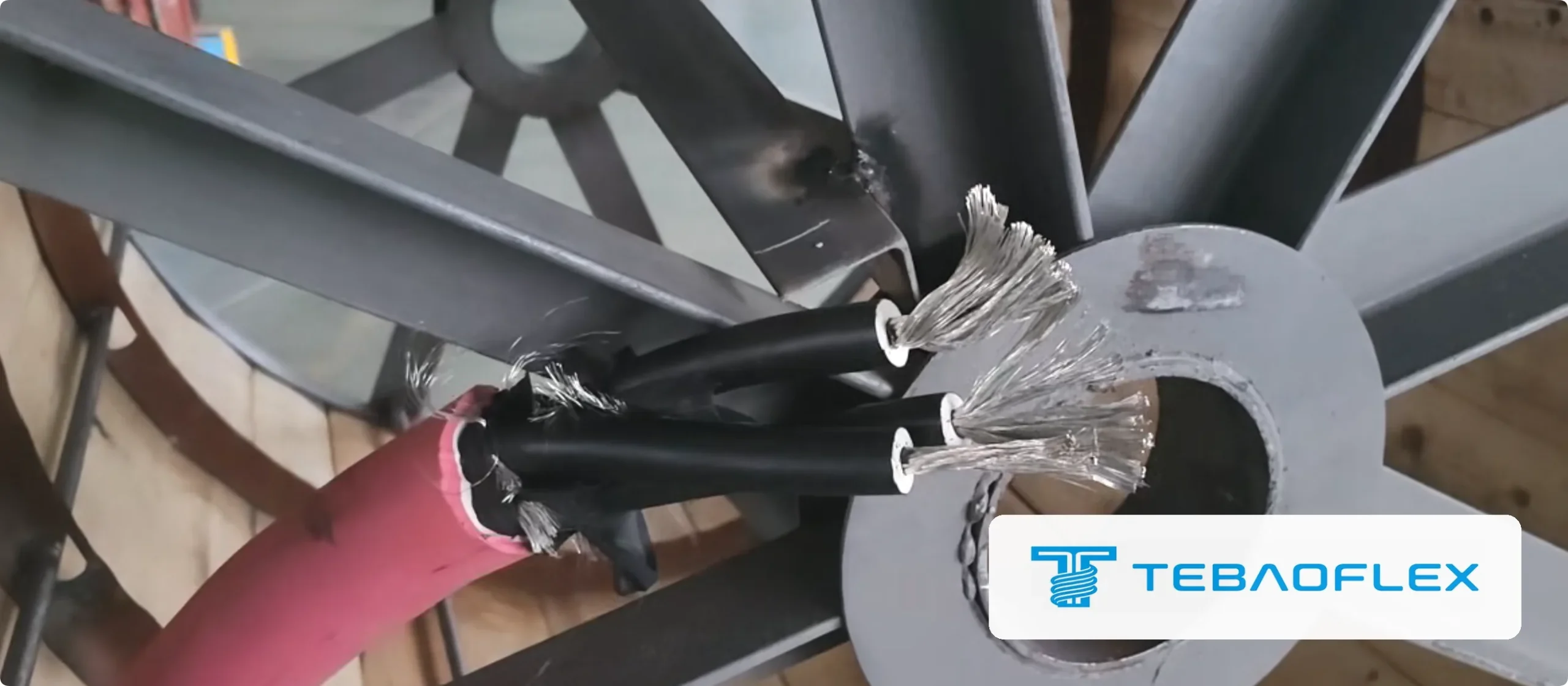
Strip the core and look along the conductor strands and the screen wires: tinned copper is silver-grey over its whole length, bare copper is copper-red. The resistance test then shows the conductor meets the limit for its size: the 35 mm² conductor of this order measured 0.529 Ω/km in the factory acceptance test report, within the 0.565 Ω/km maximum at 20 °C that IEC 60228 sets for a 35 mm² Class 5 tinned conductor.
Look at the strand surfaces after stripping, not at a saw-cut face, which shows the copper core of every strand even on tinned wire. Resistance alone cannot tell tinned from plain copper either: for 35 mm² Class 5 conductors the IEC 60228 limits are 0.554 Ω/km for plain copper and 0.565 Ω/km for tinned copper, only about 2% apart, and a conductor of either kind usually measures below both, as this one did.
How do you confirm a medium-voltage reeling cable has no broken conductors?
Continuity and voltage tests on the complete drum confirm that a medium-voltage reeling cable has no broken conductors. Each power core of this 12/20 kV cable was checked for continuity end to end, and the full drum length held 29 kV AC for 5 minutes and passed the partial discharge measurement. A conductor broken right through fails the continuity check, and insulation damaged badly enough to break down or discharge fails the voltage or partial discharge test. Broken single strands or a well-made repair can still pass, so the tests show the drum has no open conductors or insulation faults rather than proving it was never repaired.
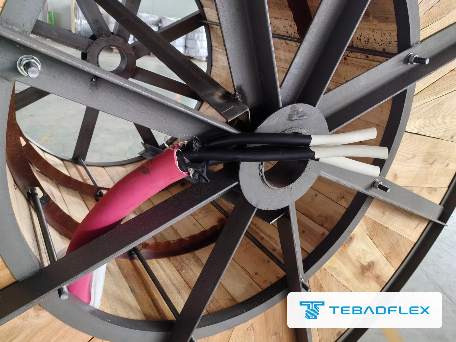
The drums of this order were supplied as continuous lengths without joints.
Why one drum shipped at 480 m: the first 20 m were cut off
The Polish bucket-wheel excavator order was for two 500 m drums of (N)TSCGECEWÖU 12/20 kV cable. On one production length, the first 20 m or so of red sheath came out of the vulcanisation line with uneven colour, because pigment from the previous batch was still in the extrusion head; after that stretch the colour was even. TEBAOFLEX judged the difference cosmetic but cut the 20 m off rather than ship it, and the drum went out at 480 m after passing the same factory acceptance test.
The buyer asked for an explanation of the short drum, and this was it. TEBAOFLEX explained the cause, the cut and the remaining length to the buyer in writing, and the test report covers both drums, 500 m and 480 m.
What to send us for a bucket-wheel excavator reeling cable quote
- Machine and reel (bucket-wheel excavator, spreader, shovel; reel drive, for example motorised, and winding, for example monospiral or multi-layer)
- Rated voltage U₀/U and the system it feeds
- Conductor arrangement: power cores, protective conductor, control cores or fibres
- The standard the order must be built and tested to
- Length per drum and number of drums
- Reel core diameter and maximum cable diameter
- Travel speed and number of layers on the reel
- Lowest and highest site temperature
- Tests you want to witness, and the partial discharge limit and test voltage
- Documents required: test report per drum, Declaration of Conformity
Questions on bucket-wheel excavator reeling cable
What does 3×35+3×25/3 mean on a medium-voltage reeling cable?
Three 35 mm² power cores plus a 25 mm² protective conductor that is divided into three equal parts. In the (N)TSCGECEWÖU cable of this order each part is the tinned copper wire screen around one power core, so every core carries its own screen and the three screens together form the protective conductor.
Is (N)TSCGECEWÖU a VDE-certified cable?
No. TEBAOFLEX writes (N) in front of the designation to mark a construction built with reference to the DIN VDE 0250 series, here DIN VDE 0250-813 as the buyer specified, rather than an approved VDE standard type; it is not a VDE certification mark. The test values for this order are those in its factory acceptance test report.
What partial discharge level is acceptable for a 12/20 kV reeling cable?
The factory acceptance test report for this order set a limit of 10 pC, and the cable measured 2.0 pC. Agree the limit and the test voltage in the order specification, because they depend on the standard the project works to.
How are the three power cores of a medium-voltage cable identified?
On this cable each 35 mm² power core is numbered 1, 2 or 3 on its insulation, so the installer can connect each core to the same phase at the excavator and at the transformer.
Can the buyer witness the factory acceptance test?
On this order the buyer's QC inspector witnessed the factory acceptance test at the TEBAOFLEX factory on 27 September 2026. State in the enquiry which tests you want to witness and which documents you need with the delivery.
Why did one drum ship at 480 m instead of 500 m?
The first 20 m or so of that production length came out of the vulcanisation line with uneven sheath colour, caused by pigment left in the extrusion head from the previous batch. TEBAOFLEX judged the colour difference cosmetic but cut the section off rather than ship it, and the remaining 480 m went through the same factory acceptance test.