







Fixed Mining Power Cable — PVC / HEPR, SWA / STA Options
Copper power cables for fixed mine distribution and equipment supply. Select the exact Polish, Czech or MGM 109 construction, with PVC or HEPR insulation and unarmoured, steel-wire or steel-tape options.
Fixed mining power cable supplies installed mine distribution circuits, machines and electrical equipment. This family groups PVC- and HEPR-insulated copper constructions rated from 0.6/1 kV to 3.6/6 kV, with separate tables for Polish, Czech and MGM 109 model designations. Choose the exact model, voltage and armouring arrangement before selecting conductor size.
The Polish selections cover unarmoured YnKGY-żo and YKGYyn-żo, round steel-wire-armoured YKGYFoyn and steel-tape-armoured YKGYFtZnyn. Their installation scope includes specific mine-area conditions and, for the armoured constructions, different shaft or excavation inclination limits. The 0.6/1 kV and 3.6/6 kV versions of YKGYFoyn also differ in conductor arrangement, metallic screening and sheath colour.
The Czech selections include solid-conductor CYKYDY-J at 0.6/1 kV, HEPR-insulated CHKCYDY and PVC-insulated CYKCYDY at 3.6/6 kV. The two medium voltage designs have a concentric copper conductor and steel-wire armour, with separate thermal limits. MGM 109 Type 1012, 1013 and 1014 use single wire armour; Types 1023 and 1024 use two layers. At 1.9/3.3 kV, Type 3013 is single armoured, Type 3023 is double armoured and Type 3123 adds individual copper-backed tape screens.
Use the model-specific size, bend-radius and electrical tables to plan the cable route and terminations. Provide the supply voltage, complete conductor configuration, mine classification, armouring requirement, route length and required drum lengths with the enquiry. Check support spacing, pulling arrangements and cable-entry space together with the chosen cable diameter.
Explore the mining and tunneling cable range for related configurations.
For underground gallery distribution and vertical shaft drop routes requiring metallic armouring, compare these mining power cables: YnOGY / YnOGYek / YnOGYekm PVC Mining Cable 0.6/1 kV (for 0.6/1 kV Polish-standard PVC mining distribution cables with unarmoured, steel tape, or round steel wire armour options); Mine Borehole & Shaft Self-Supporting Armoured Drop Cable (0.6/1–15 kV) (for 0.6/1 kV to 15 kV self-supporting steel-wire-armoured borehole and vertical shaft feeders). Verify insulation thermal class (PVC vs HEPR), armour tensile rating, and gallery flame-retardant rules before ordering.
Construction
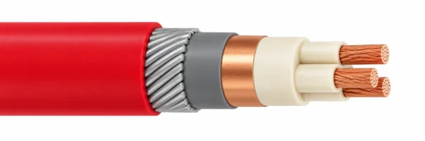
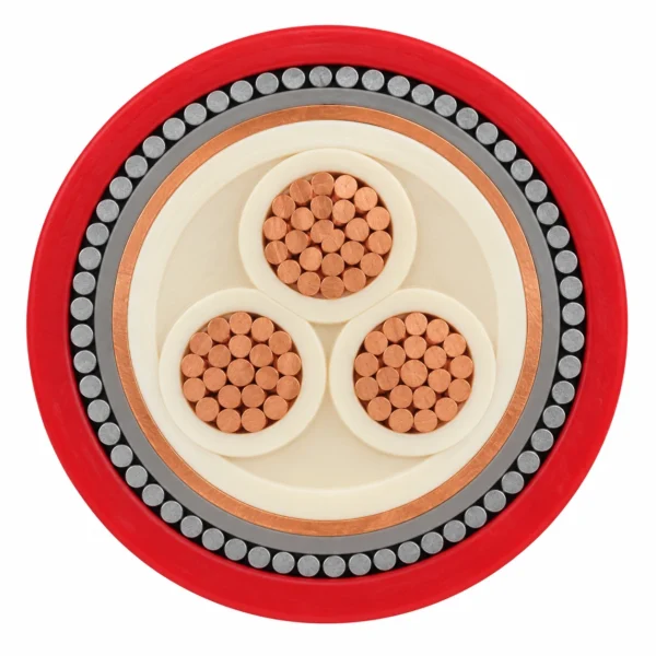
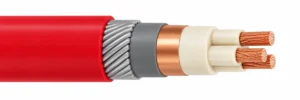
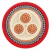
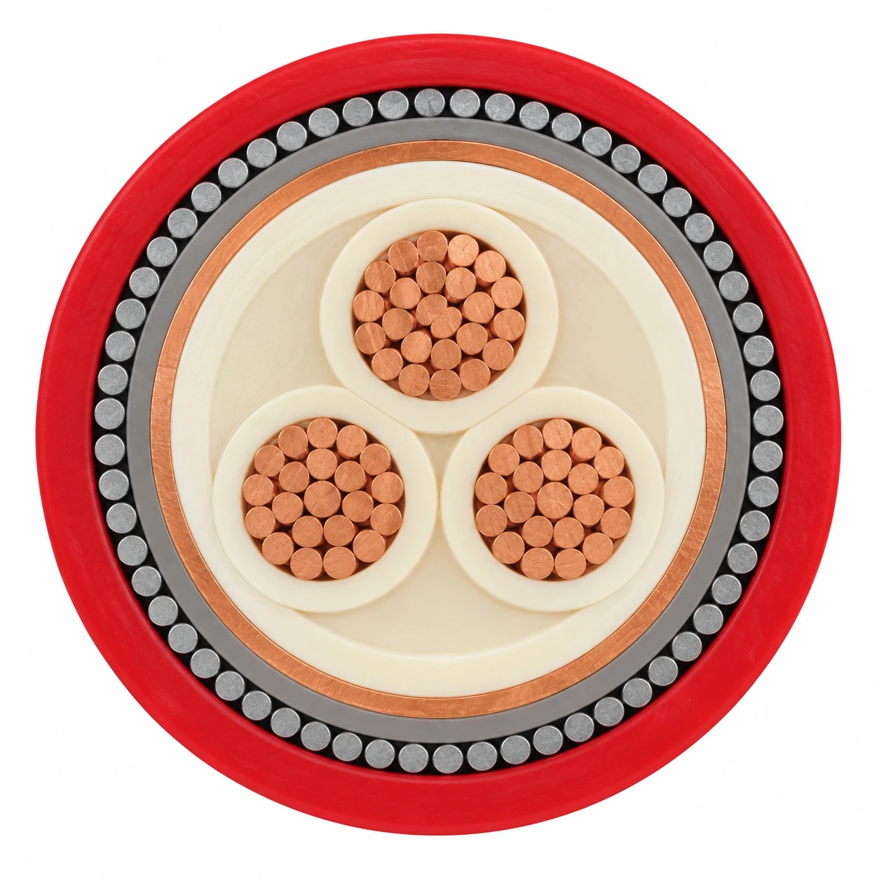
The representative image shows YKGYFoyn 3 × 35/16 mm² at 3.6/6 kV: three compacted copper phase conductors in a triangular arrangement, PVC insulation and bedding, a common copper-tape screen, a separating PVC layer, one layer of round steel-wire armour and a red PVC outer sheath.
| Component | Material and construction |
|---|---|
| Copper conductors | Class 1 or Class 2 according to the selected model. CHKCYDY, CYKCYDY and medium voltage MGM designs use Class 2; the listed CYKYDY-J designs use Class 1. |
| Insulation selection | PVC for the Polish, CYKYDY-J, CYKCYDY and MGM constructions; HEPR for CHKCYDY. |
| Unarmoured Polish constructions | YnKGY-żo has PVC insulation and outer sheath. YKGYyn-żo adds an inner PVC sheath. Both include a green-yellow protective core. |
| YKGYFoyn armour and screen | One layer of round galvanised steel wires. The 3.6/6 kV construction has a common copper-tape screen and PVC separating layer. |
| YKGYFtZnyn 3.6/6 kV | Common copper-tape screen, PVC separator and galvanised steel-tape armour. |
| Czech medium voltage concentric layer | Semiconductive tape, round copper wires, copper tape and plastic tape outside the insulated core assembly, followed by the separation layer and single steel-wire armour. |
| MGM single and double wire armour | Types 1012/1013/1014 and 3013: single layer; Types 1023/1024, 3023 and 3123: two layers. PVC bedding and special PVC outer sheath; optional galvanised steel-tape separator. |
| MGM Type 3123 screening | Semiconducting separator layer and copper-backed tape screen around each insulated core, before the common bedding and two armour layers. |
| Outer-sheath identification | Polish 0.6/1 kV designs: yellow; Polish and Czech 3.6/6 kV designs: red; CYKYDY-J: black. State the required MGM sheath colour with the order. |
Applications
Select these constructions for supported fixed power routes. The model tables preserve the differences in mine-area scope, insulation, armour and permissible installation conditions.
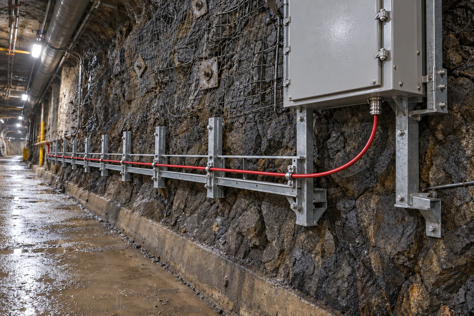
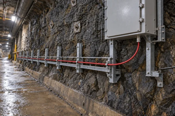
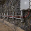
- Fixed mine distribution and machinery supply routes with mechanically protected cable entries and suitable support.
- YnKGY-żo and YKGYyn-żo: open-pit, strip and underground mine equipment in areas without an explosion hazard, including the specified class A coal-dust excavation scope.
- YKGYFoyn: mine feeders and shafts or inclined excavations up to 90° within the selected voltage construction’s scope.
- YKGYFtZnyn 3.6/6 kV: fixed mine power transmission in excavations with inclination up to 45°.
- CYKYDY-J: fixed power networks requiring additional mechanical protection, including underground, outdoor, indoor and duct routes.
- CHKCYDY and CYKCYDY: fixed medium voltage distribution in industrial areas, buildings and associated mine infrastructure.
- MGM 109: fixed supply to machines and equipment on the surface and in deep mines; specify the site’s gas, dust and acceptance requirements.
- Use a separately selected flexible mining cable for trailing, continuous reeling or repetitive machine movement.
For fixed underground mine power routing guidelines and British-standard roadway distribution cables, consult these references: Armoured and Static Mining Cable: Fixed Distribution Routes (covering SWA vs STA mechanical protection, earthing conductance, and roadway suspension spacing); Type 20 / Type 21 BS 6708 640/1100 V Armoured Mining Cable (for 640/1100 V BS 6708 Type 20 single-wire-armoured and Type 21 double-wire-armoured roadway and face distribution cables). Confirm fault-current armour conductance, coupler compatibility, and water-blocking needs.
Specifications
| Parameter | Value |
|---|---|
| Duty | Fixed installation; model-specific armouring and mine-area selection. |
| Voltage families | Polish/Czech low voltage: 0.6/1 kV; MGM low voltage: 600/1000 V; MGM medium voltage: 1900/3300 V; Polish/Czech medium voltage: 3.6/6 kV. |
| Insulation and temperature | PVC models generally have a 70°C conductor limit where specified. CHKCYDY HEPR has a 90°C conductor limit. Use the thermal table for each construction. |
| Armouring choices | Unarmoured, single round steel wire, double round steel wire or steel tape, according to the exact designation. |
| Screen selection | Unscreened, common copper-tape screen, concentric copper conductor or individual copper-backed tape screens, according to model. |
| Bend allowance | Use the model-specific multiple of D or the stated minimum bend radius in each MGM row. |
| Ordering identification | Give the model, U₀/U, full core configuration, insulation, armour and applicable mine-area requirements. |
| Model | Rated voltage U₀/U | Insulation | Screen / concentric layer | Armour | Test voltage |
|---|---|---|---|---|---|
| YnKGY-żo | 0.6/1 kV | PVC | None | None | 3.5 kV |
| YKGYyn-żo | 0.6/1 kV | PVC | None | None | 3.5 kV |
| YKGYFoyn | 0.6/1 kV | PVC | Protective components to configuration | Single round steel wire | 3.5 kV |
| YKGYFoyn | 3.6/6 kV | PVC | Common copper tape | Single round steel wire | 11 kV |
| YKGYFtZnyn | 3.6/6 kV | PVC | Common copper tape | Galvanised steel tape | 11 kV |
| CYKYDY-J | 0.6/1 kV | PVC DIV1 | None | Single round steel wire | By ordered specification |
| CHKCYDY | 3.6/6 kV | HEPR | Concentric copper conductor | Single round steel wire | By ordered specification |
| CYKCYDY | 3.6/6 kV | PVC DIV6 | Concentric copper conductor | Single round steel wire | 11 kV AC, 5 min, 50 Hz |
| MGM 109 Type 1012 / 1013 / 1014 | 600/1000 V | PVC | None | Single steel wire | 3 kV |
| MGM 109 Type 1023 / 1024 | 600/1000 V | PVC | None | Double steel wire | 3 kV |
| MGM 109 Type 3013 | 1900/3300 V | PVC | None | Single steel wire | 10 kV |
| MGM 109 Type 3023 | 1900/3300 V | PVC | None | Double steel wire | 10 kV |
| MGM 109 Type 3123 | 1900/3300 V | PVC | Individual copper-backed tapes | Double steel wire | 6 kV |
| Construction | Maximum conductor temperature | Minimum fixed ambient | Minimum laying temperature | Short-circuit temperature | Minimum bend radius |
|---|---|---|---|---|---|
| YnKGY-żo / YKGYyn-żo | 70°C | −30°C | −5°C | By ordered specification | 10 × D |
| YKGYFoyn 0.6/1 kV | 70°C | −30°C | −5°C | By ordered specification | 10 × D |
| YKGYFoyn / YKGYFtZnyn 3.6/6 kV | 70°C | −30°C | By installation specification | By ordered specification | 10 × D |
| CYKYDY-J | 70°C | −20°C | −5°C | 160°C | 15 × D |
| CHKCYDY | 90°C | −30°C | 0°C | 250°C | 12 × D for circular conductors |
| CYKCYDY | 70°C | −30°C | 0°C | 150°C | 12 × D for circular conductors |
| MGM 109 constructions | By ordered specification | By installation specification | By installation specification | By ordered specification | Configuration-specific mm values below |
| Model and conductor configuration | Max. overall diameter (mm) | Calculated weight (kg/km) |
|---|---|---|
| YnKGY-żo 3 × 1.5 mm² | 10.2 | 153 |
| YnKGY-żo 4 × 1.5 mm² | 11.1 | 180 |
| YnKGY-żo 5 × 1.5 mm² | 11.8 | 215 |
| YnKGY-żo 3 × 2.5 mm² | 11.0 | 195 |
| YnKGY-żo 4 × 2.5 mm² | 12.0 | 235 |
| YnKGY-żo 5 × 2.5 mm² | 12.9 | 280 |
| YnKGY-żo 3 × 4 mm² | 12.9 | 280 |
| YnKGY-żo 4 × 4 mm² | 14.2 | 345 |
| YnKGY-żo 5 × 4 mm² | 15.2 | 410 |
| YnKGY-żo 3 × 6 mm² | 13.9 | 355 |
| YnKGY-żo 4 × 6 mm² | 15.4 | 440 |
| YnKGY-żo 5 × 6 mm² | 16.6 | 525 |
| YnKGY-żo 3 × 10 mm² | 16.4 | 520 |
| YnKGY-żo 4 × 10 mm² | 18.1 | 655 |
| YnKGY-żo 5 × 10 mm² | 19.6 | 790 |
| Model and conductor configuration | Max. overall diameter (mm) | Calculated weight (kg/km) |
|---|---|---|
| YKGYyn-żo 3 × 1.5 mm² | 13.9 | 260 |
| YKGYyn-żo 4 × 1.5 mm² | 14.8 | 300 |
| YKGYyn-żo 5 × 1.5 mm² | 15.6 | 350 |
| YKGYyn-żo 3 × 2.5 mm² | 14.7 | 310 |
| YKGYyn-żo 4 × 2.5 mm² | 15.8 | 355 |
| YKGYyn-żo 5 × 2.5 mm² | 16.6 | 425 |
| YKGYyn-żo 3 × 4 mm² | 16.6 | 410 |
| YKGYyn-żo 4 × 4 mm² | 17.9 | 480 |
| YKGYyn-żo 5 × 4 mm² | 19.0 | 580 |
| YKGYyn-żo 3 × 6 mm² | 17.7 | 490 |
| YKGYyn-żo 4 × 6 mm² | 19.1 | 590 |
| YKGYyn-żo 5 × 6 mm² | 20.3 | 720 |
| YKGYyn-żo 3 × 10 mm² | 20.1 | 560 |
| YKGYyn-żo 4 × 10 mm² | 21.9 | 660 |
| YKGYyn-żo 5 × 10 mm² | 23.3 | 820 |
| Model and conductor configuration | Max. overall diameter (mm) | Calculated weight (kg/km) |
|---|---|---|
| YKGYFoyn 3 × 10/6 mm² | 25.9 | 1600 |
| YKGYFoyn 3 × 16/16 mm² | 28.4 | 2040 |
| YKGYFoyn 3 × 25/16 mm² | 32.6 | 2600 |
| YKGYFoyn 3 × 35/16 mm² | 34.3 | 2990 |
| YKGYFoyn 3 × 50/16 mm² | 37.9 | 3680 |
| YKGYFoyn 3 × 70/25 mm² | 43.2 | 4780 |
| YKGYFoyn 3 × 95/25 mm² | 48.6 | 5950 |
| YKGYFoyn 3 × 120/35 mm² | 52.9 | 7140 |
| Model and conductor configuration | Calculated overall diameter (mm) | Calculated weight (kg/km) |
|---|---|---|
| YKGYFoyn 3 × 10/10 mm² | 46.8 | 4715 |
| YKGYFoyn 3 × 16/10 mm² | 49.6 | 5290 |
| YKGYFoyn 3 × 25/14 mm² | 52.5 | 5963 |
| YKGYFoyn 3 × 35/16 mm² | 53.9 | 6460 |
| YKGYFoyn 3 × 50/18 mm² | 59.2 | 8315 |
| YKGYFoyn 3 × 70/18 mm² | 64.5 | 9753 |
| YKGYFoyn 3 × 95/20 mm² | 68.8 | 11178 |
| YKGYFoyn 3 × 120/22 mm² | 71.3 | 12670 |
| YKGYFoyn 3 × 150/24 mm² | 75.5 | 14455 |
| YKGYFoyn 3 × 185/27 mm² | 84.5 | 18462 |
| Model and conductor configuration | Calculated overall diameter (mm) | Calculated weight (kg/km) |
|---|---|---|
| YKGYFtZnyn 3 × 10/10 mm² | 38.7 | 2298 |
| YKGYFtZnyn 3 × 16/10 mm² | 41.5 | 2711 |
| YKGYFtZnyn 3 × 25/14 mm² | 44.5 | 3377 |
| YKGYFtZnyn 3 × 35/16 mm² | 47.2 | 4241 |
| YKGYFtZnyn 3 × 50/18 mm² | 51.0 | 5022 |
| YKGYFtZnyn 3 × 70/18 mm² | 55.0 | 5989 |
| YKGYFtZnyn 3 × 95/20 mm² | 60.0 | 7240 |
| YKGYFtZnyn 3 × 120/22 mm² | 63.8 | 8272 |
| YKGYFtZnyn 3 × 150/24 mm² | 69.3 | 9948 |
| YKGYFtZnyn 3 × 185/27 mm² | 72.7 | 11978 |
| Power conductor (mm²) | Resistance (Ω/km) | Inductance (mH/km) | Reactance (Ω/km) | Reference current (A) | 1 s short-circuit capacity (kA) |
|---|---|---|---|---|---|
| 1.5 | 12.1 | 0.34 | 0.107 | 19 | 0.17 |
| 2.5 | 7.41 | 0.32 | 0.099 | 27 | 0.29 |
| 4 | 4.61 | 0.32 | 0.100 | 37 | 0.46 |
| 6 | 3.08 | 0.30 | 0.095 | 47 | 0.69 |
| 10 | 1.83 | 0.28 | 0.089 | 62 | 1.15 |
| Power conductor (mm²) | Resistance (Ω/km) | Inductance (mH/km) | Reactance (Ω/km) | Reference current (A) | 1 s short-circuit capacity (kA) |
|---|---|---|---|---|---|
| 10 | 1.83 | 0.31 | 0.098 | 64 | 1.15 |
| 16 | 1.15 | 0.30 | 0.092 | 86 | 1.84 |
| 25 | 0.727 | 0.30 | 0.092 | 113 | 2.88 |
| 35 | 0.524 | 0.29 | 0.090 | 139 | 4.03 |
| 50 | 0.387 | 0.28 | 0.088 | 173 | 5.75 |
| 70 | 0.268 | 0.26 | 0.085 | 212 | 8.05 |
| 95 | 0.193 | 0.26 | 0.084 | 257 | 10.93 |
| 120 | 0.153 | 0.26 | 0.083 | 294 | 13.80 |
| Power conductor (mm²) | Resistance (Ω/km) | Inductance (mH/km) | Reactance (Ω/km) | Capacitance to earth (µF/km) | To-earth current reference (A/km) | 1 s short-circuit capacity (kA) | Reference continuous current (A) |
|---|---|---|---|---|---|---|---|
| 10 | 1.83 | 0.400 | 0.126 | 0.11 | 0.35 | 1.15 | 68 |
| 16 | 1.15 | 0.372 | 0.117 | 0.11 | 0.37 | 1.84 | 87 |
| 25 | 0.727 | 0.349 | 0.110 | 0.12 | 0.40 | 2.88 | 113 |
| 35 | 0.524 | 0.338 | 0.106 | 0.13 | 0.41 | 4.03 | 137 |
| 50 | 0.387 | 0.317 | 0.100 | 0.13 | 0.43 | 5.75 | 164 |
| 70 | 0.268 | 0.299 | 0.094 | 0.14 | 0.45 | 8.05 | 202 |
| 95 | 0.193 | 0.286 | 0.090 | 0.15 | 0.47 | 10.93 | 245 |
| 120 | 0.153 | 0.278 | 0.087 | 0.15 | 0.49 | 13.8 | 281 |
| 150 | 0.124 | 0.268 | 0.084 | 0.15 | 0.50 | 17.25 | 319 |
| 185 | 0.0991 | 0.262 | 0.082 | 0.16 | 0.51 | 21.28 | 369 |
| Power conductor (mm²) | Resistance (Ω/km) | Inductance (mH/km) | Reactance (Ω/km) | Capacitance to earth (µF/km) | To-earth current reference (A/km) | 1 s short-circuit capacity (kA) | Reference continuous current (A) |
|---|---|---|---|---|---|---|---|
| 10 | 1.83 | 0.400 | 0.126 | 0.11 | 0.35 | 1.15 | 66 |
| 16 | 1.15 | 0.372 | 0.117 | 0.11 | 0.37 | 1.84 | 85 |
| 25 | 0.727 | 0.349 | 0.110 | 0.12 | 0.40 | 2.88 | 110 |
| 35 | 0.524 | 0.338 | 0.106 | 0.13 | 0.41 | 4.03 | 133 |
| 50 | 0.387 | 0.317 | 0.100 | 0.13 | 0.43 | 5.75 | 160 |
| 70 | 0.268 | 0.299 | 0.094 | 0.14 | 0.45 | 8.05 | 197 |
| 95 | 0.193 | 0.286 | 0.090 | 0.15 | 0.47 | 10.93 | 240 |
| 120 | 0.153 | 0.278 | 0.087 | 0.15 | 0.49 | 13.8 | 276 |
| 150 | 0.124 | 0.268 | 0.084 | 0.15 | 0.50 | 17.25 | 314 |
| 185 | 0.0991 | 0.262 | 0.082 | 0.16 | 0.51 | 21.28 | 360 |
| Model and conductor configuration | Approx. overall diameter (mm) | Approx. weight (kg/km) | Max. conductor resistance at 20°C (Ω/km) |
|---|---|---|---|
| CYKYDY-J 4 × 2.5RE mm² | 15.8 | 534 | 7.41 |
| CYKYDY-J 5 × 2.5RE mm² | 16.7 | 610 | 7.41 |
| CYKYDY-J 12 × 1.5RE mm² | 20.0 | 823 | 12.1 |
| CYKYDY-J 12 × 2.5RE mm² | 21.6 | 1003 | 7.41 |
| CYKYDY-J 37 × 2.5RE mm² | 32.0 | 2327 | 7.41 |
| Model and conductor configuration | Approx. overall diameter (mm) | Approx. weight (kg/km) | Max. conductor resistance at 20°C (Ω/km) |
|---|---|---|---|
| CHKCYDY 3 × 70/50 mm² | 51.8 | 5993 | 0.268/0.387 |
| CHKCYDY 3 × 95/50 mm² | 55.4 | 7095 | 0.193/0.387 |
| CHKCYDY 3 × 120/50 mm² | 58.9 | 8175 | 0.153/0.387 |
| CHKCYDY 3 × 150/50 mm² | 62 | 9233 | 0.124/0.387 |
| Model and conductor configuration | Approx. overall diameter (mm) | Approx. weight (kg/km) | Max. conductor resistance at 20°C (Ω/km) |
|---|---|---|---|
| CYKCYDY 3 × 50SM/25 mm² | 48.9 | 5286 | 0.387/0.727 |
| CYKCYDY 3 × 95SM/50 mm² | 56.8 | 7553 | 0.193/0.387 |
| CYKCYDY 3 × 150SM/50 mm² | 63.5 | 11510 | 0.124/0.387 |
| Model and conductor configuration | Insulation (mm) | Inner sheath (mm) | Diameter over inner sheath (mm) | Outer sheath (mm) | Min. overall diameter (mm) | Max. overall diameter (mm) | Min. bend radius (mm) | Approx. weight (kg/km) | Copper weight (kg/km) |
|---|---|---|---|---|---|---|---|---|---|
| MGM 109 Type 1012 2 × 1.5 mm² | 0.8 | 0.8 | 7.0 | 1.3 | 9.7 | 13.7 | 124 | 320 | 30 |
| MGM 109 Type 1012 2 × 2.5 mm² | 0.8 | 0.8 | 8.2 | 1.4 | 11.1 | 15.1 | 136 | 395 | 50 |
| MGM 109 Type 1012 2 × 4 mm² | 0.8 | 0.8 | 10.2 | 1.4 | 13.1 | 17.1 | 154 | 480 | 80 |
| MGM 109 Type 1012 2 × 6 mm² | 0.8 | 0.8 | 11.3 | 1.5 | 14.5 | 18.5 | 167 | 620 | 120 |
| MGM 109 Type 1012 2 × 10 mm² | 1.0 | 0.8 | 14.0 | 1.6 | 18.1 | 22.1 | 199 | 950 | 220 |
| MGM 109 Type 1012 2 × 16 mm² | 1.0 | 0.8 | 15.8 | 1.6 | 19.9 | 23.9 | 216 | 1280 | 380 |
| Model and conductor configuration | Continuous current at 25°C ambient (A) | Max. phase/earth conductor DC resistance at 20°C (Ω/km) | Max. armour DC resistance at 20°C (Ω/km) |
|---|---|---|---|
| MGM 109 Type 1012 2 × 1.5 mm² | 18 | 12.1 | 20.17 |
| MGM 109 Type 1012 2 × 2.5 mm² | 26 | 7.41 | 12.30 |
| MGM 109 Type 1012 2 × 4 mm² | 34 | 4.61 | 7.68 |
| MGM 109 Type 1012 2 × 6 mm² | 44 | 3.08 | 5.13 |
| MGM 109 Type 1012 2 × 10 mm² | 61 | 1.83 | 3.05 |
| MGM 109 Type 1012 2 × 16 mm² | 82 | 1.15 | 1.92 |
| Model and conductor configuration | Insulation (mm) | Inner sheath (mm) | Diameter over inner sheath (mm) | Outer sheath (mm) | Min. overall diameter (mm) | Max. overall diameter (mm) | Min. bend radius (mm) | Approx. weight (kg/km) | Copper weight (kg/km) |
|---|---|---|---|---|---|---|---|---|---|
| MGM 109 Type 1013 3 × 1.5 mm² | 0.8 | 0.8 | 7.4 | 1.4 | 9.7 | 13.7 | 124 | 350 | 45 |
| MGM 109 Type 1013 3 × 2.5 mm² | 0.8 | 0.8 | 8.8 | 1.4 | 11.1 | 15.1 | 136 | 420 | 75 |
| MGM 109 Type 1013 3 × 4 mm² | 0.8 | 0.8 | 10.9 | 1.4 | 13.1 | 17.1 | 154 | 560 | 120 |
| MGM 109 Type 1013 3 × 6 mm² | 0.8 | 0.8 | 12.0 | 1.5 | 14.5 | 18.5 | 167 | 780 | 190 |
| MGM 109 Type 1013 3 × 10 mm² | 1.0 | 0.8 | 15.0 | 1.6 | 18.1 | 22.1 | 199 | 1120 | 310 |
| MGM 109 Type 1013 3 × 16 mm² | 1.0 | 0.8 | 16.6 | 1.6 | 20.7 | 24.7 | 223 | 1400 | 530 |
| MGM 109 Type 1013 3 × 25 mm² | 1.2 | 1.0 | 20.3 | 1.7 | 25.3 | 29.3 | 264 | 2150 | 810 |
| MGM 109 Type 1013 3 × 35 mm² | 1.2 | 1.0 | 22.5 | 1.8 | 27.9 | 31.9 | 288 | 2450 | 1160 |
| MGM 109 Type 1013 3 × 50 mm² | 1.4 | 1.0 | 26.2 | 1.9 | 32.2 | 36.2 | 326 | 3400 | 1720 |
| MGM 109 Type 1013 3 × 70 mm² | 1.4 | 1.2 | 30.0 | 2.0 | 36.4 | 40.4 | 364 | 4420 | 2340 |
| MGM 109 Type 1013 3 × 95 mm² | 1.6 | 1.2 | 34.8 | 2.1 | 41.6 | 45.6 | 411 | 5800 | 3200 |
| Model and conductor configuration | Continuous current at 25°C ambient (A) | Max. phase/earth conductor DC resistance at 20°C (Ω/km) | Max. armour DC resistance at 20°C (Ω/km) |
|---|---|---|---|
| MGM 109 Type 1013 3 × 1.5 mm² | 18 | 12.1 | 20.17 |
| MGM 109 Type 1013 3 × 2.5 mm² | 26 | 7.41 | 12.30 |
| MGM 109 Type 1013 3 × 4 mm² | 34 | 4.61 | 7.68 |
| MGM 109 Type 1013 3 × 6 mm² | 44 | 3.08 | 5.13 |
| MGM 109 Type 1013 3 × 10 mm² | 61 | 1.83 | 3.05 |
| MGM 109 Type 1013 3 × 16 mm² | 82 | 1.15 | 1.92 |
| MGM 109 Type 1013 3 × 25 mm² | 108 | 0.727 | 1.21 |
| MGM 109 Type 1013 3 × 35 mm² | 135 | 0.524 | 0.873 |
| MGM 109 Type 1013 3 × 50 mm² | 168 | 0.387 | 0.645 |
| MGM 109 Type 1013 3 × 70 mm² | 207 | 0.268 | 0.447 |
| MGM 109 Type 1013 3 × 95 mm² | 250 | 0.193 | 0.322 |
| Model and conductor configuration | Insulation (mm) | Inner sheath (mm) | Diameter over inner sheath (mm) | Outer sheath (mm) | Min. overall diameter (mm) | Max. overall diameter (mm) | Min. bend radius (mm) | Approx. weight (kg/km) | Copper weight (kg/km) |
|---|---|---|---|---|---|---|---|---|---|
| MGM 109 Type 1014 4 × 1.5 mm² | 0.8 | 0.8 | 8.1 | 1.4 | 11.0 | 15.0 | 135 | 420 | 60 |
| MGM 109 Type 1014 4 × 2.5 mm² | 0.8 | 0.8 | 9.5 | 1.4 | 12.5 | 16.5 | 149 | 500 | 100 |
| MGM 109 Type 1014 4 × 4 mm² | 0.8 | 0.8 | 11.9 | 1.5 | 15.8 | 19.8 | 179 | 750 | 160 |
| MGM 109 Type 1014 4 × 6 mm² | 0.8 | 0.8 | 13.2 | 1.5 | 17.2 | 21.2 | 191 | 820 | 240 |
| MGM 109 Type 1014 4 × 10 mm² | 1.0 | 0.8 | 16.5 | 1.6 | 20.8 | 24.8 | 224 | 1350 | 400 |
| MGM 109 Type 1014 4 × 16 mm² | 1.0 | 1.0 | 18.7 | 1.7 | 23.9 | 27.9 | 252 | 1900 | 660 |
| MGM 109 Type 1014 4 × 25 mm² | 1.2 | 1.0 | 22.6 | 1.8 | 28.0 | 32.0 | 288 | 2610 | 1050 |
| MGM 109 Type 1014 4 × 35 mm² | 1.2 | 1.0 | 25.0 | 1.9 | 30.6 | 34.6 | 312 | 3100 | 1460 |
| MGM 109 Type 1014 4 × 50 mm² | 1.4 | 1.2 | 29.6 | 2.0 | 36.2 | 40.2 | 362 | 4300 | 2090 |
| MGM 109 Type 1014 4 × 70 mm² | 1.4 | 1.2 | 33.4 | 2.1 | 40.2 | 44.2 | 398 | 5400 | 3010 |
| MGM 109 Type 1014 4 × 95 mm² | 1.6 | 1.2 | 38.7 | 2.2 | 45.7 | 49.7 | 448 | 7000 | 4100 |
| Model and conductor configuration | Continuous current at 25°C ambient (A) | Max. phase/earth conductor DC resistance at 20°C (Ω/km) | Max. armour DC resistance at 20°C (Ω/km) |
|---|---|---|---|
| MGM 109 Type 1014 4 × 1.5 mm² | 18 | 12.1 | 20.17 |
| MGM 109 Type 1014 4 × 2.5 mm² | 26 | 7.41 | 12.30 |
| MGM 109 Type 1014 4 × 4 mm² | 34 | 4.61 | 7.68 |
| MGM 109 Type 1014 4 × 6 mm² | 44 | 3.08 | 5.13 |
| MGM 109 Type 1014 4 × 10 mm² | 61 | 1.83 | 3.05 |
| MGM 109 Type 1014 4 × 16 mm² | 82 | 1.15 | 1.92 |
| MGM 109 Type 1014 4 × 25 mm² | 108 | 0.727 | 1.21 |
| MGM 109 Type 1014 4 × 35 mm² | 135 | 0.524 | 0.873 |
| MGM 109 Type 1014 4 × 50 mm² | 168 | 0.387 | 0.645 |
| MGM 109 Type 1014 4 × 70 mm² | 207 | 0.268 | 0.447 |
| MGM 109 Type 1014 4 × 95 mm² | 250 | 0.193 | 0.322 |
| Model and conductor configuration | Insulation (mm) | Inner sheath (mm) | Diameter over inner sheath (mm) | Outer sheath (mm) | Min. overall diameter (mm) | Max. overall diameter (mm) | Min. bend radius (mm) | Approx. weight (kg/km) | Copper weight (kg/km) |
|---|---|---|---|---|---|---|---|---|---|
| MGM 109 Type 1023 3 × 1.5 mm² | 0.8 | 0.8 | 7.4 | 1.4 | 9.7 | 13.7 | 124 | 350 | 45 |
| MGM 109 Type 1023 3 × 2.5 mm² | 0.8 | 0.8 | 10.3 | 1.5 | 16.3 | 20.3 | 203 | 750 | 75 |
| MGM 109 Type 1023 3 × 4 mm² | 0.8 | 0.8 | 12.4 | 1.6 | 18.6 | 22.6 | 226 | 910 | 120 |
| MGM 109 Type 1023 3 × 6 mm² | 0.8 | 0.8 | 13.6 | 1.6 | 21.4 | 25.4 | 254 | 1300 | 190 |
| MGM 109 Type 1023 3 × 10 mm² | 1.0 | 0.8 | 16.5 | 1.7 | 26.5 | 30.5 | 305 | 1700 | 310 |
| Model and conductor configuration | Continuous current at 25°C ambient (A) | Max. phase/earth conductor DC resistance at 20°C (Ω/km) | Max. armour DC resistance at 20°C (Ω/km) |
|---|---|---|---|
| MGM 109 Type 1023 3 × 1.5 mm² | 18 | 12.1 | 20.17 |
| MGM 109 Type 1023 3 × 2.5 mm² | 26 | 7.41 | 9.71 |
| MGM 109 Type 1023 3 × 4 mm² | 34 | 4.61 | 6.15 |
| MGM 109 Type 1023 3 × 6 mm² | 44 | 3.08 | 4.11 |
| MGM 109 Type 1023 3 × 10 mm² | 61 | 1.83 | 2.44 |
| Model and conductor configuration | Insulation (mm) | Inner sheath (mm) | Diameter over inner sheath (mm) | Outer sheath (mm) | Min. overall diameter (mm) | Max. overall diameter (mm) | Min. bend radius (mm) | Approx. weight (kg/km) | Copper weight (kg/km) |
|---|---|---|---|---|---|---|---|---|---|
| MGM 109 Type 1024 4 × 1.5 mm² | 0.8 | 0.8 | 9.6 | 1.5 | 15.5 | 19.5 | 195 | 750 | 60 |
| MGM 109 Type 1024 4 × 2.5 mm² | 0.8 | 0.8 | 11.1 | 1.5 | 17.1 | 21.1 | 211 | 850 | 100 |
| MGM 109 Type 1024 4 × 4 mm² | 0.8 | 0.8 | 13.4 | 1.6 | 21.2 | 25.2 | 252 | 1250 | 160 |
| MGM 109 Type 1024 4 × 6 mm² | 0.8 | 0.8 | 14.8 | 1.7 | 22.8 | 26.8 | 268 | 1480 | 240 |
| MGM 109 Type 1024 4 × 10 mm² | 1.0 | 0.8 | 18.1 | 1.8 | 26.2 | 30.2 | 302 | 1980 | 385 |
| Model and conductor configuration | Continuous current at 25°C ambient (A) | Max. phase/earth conductor DC resistance at 20°C (Ω/km) | Max. armour DC resistance at 20°C (Ω/km) |
|---|---|---|---|
| MGM 109 Type 1024 4 × 1.5 mm² | 18 | 12.1 | 16.10 |
| MGM 109 Type 1024 4 × 2.5 mm² | 26 | 7.41 | 9.71 |
| MGM 109 Type 1024 4 × 4 mm² | 34 | 4.61 | 6.15 |
| MGM 109 Type 1024 4 × 6 mm² | 44 | 3.08 | 4.11 |
| MGM 109 Type 1024 4 × 10 mm² | 61 | 1.83 | 2.44 |
| Model and conductor configuration | Insulation (mm) | Inner sheath (mm) | Diameter over inner sheath (mm) | Outer sheath (mm) | Min. overall diameter (mm) | Max. overall diameter (mm) | Min. bend radius (mm) | Approx. weight (kg/km) | Copper weight (kg/km) |
|---|---|---|---|---|---|---|---|---|---|
| MGM 109 Type 3013 3 × 50 mm² | 2.2 | 1.8 | 31.2 | 2.1 | 38.0 | 42.0 | 378 | 4100 | 1600 |
| MGM 109 Type 3013 3 × 70 mm² | 2.2 | 1.8 | 34.7 | 2.2 | 41.5 | 45.5 | 410 | 5150 | 2300 |
| MGM 109 Type 3013 3 × 95 mm² | 2.2 | 1.8 | 38.5 | 2.3 | 45.7 | 49.7 | 448 | 6150 | 3200 |
| MGM 109 Type 3013 3 × 120 mm² | 2.2 | 2.2 | 42.5 | 2.4 | 50.7 | 54.7 | 493 | 7750 | 4000 |
| MGM 109 Type 3013 3 × 150 mm² | 2.2 | 2.2 | 46.6 | 2.5 | 55.0 | 59.0 | 531 | 9000 | 5000 |
| MGM 109 Type 3013 3 × 185 mm² | 2.2 | 2.2 | 50.5 | 2.6 | 58.9 | 62.9 | 567 | 10500 | 6230 |
| Model and conductor configuration | Continuous current at 25°C ambient (A) | Max. phase/earth conductor DC resistance at 20°C (Ω/km) | Max. armour DC resistance at 20°C (Ω/km) |
|---|---|---|---|
| MGM 109 Type 3013 3 × 50 mm² | 168 | 0.387 | 0.645 |
| MGM 109 Type 3013 3 × 70 mm² | 207 | 0.268 | 0.447 |
| MGM 109 Type 3013 3 × 95 mm² | 250 | 0.193 | 0.322 |
| MGM 109 Type 3013 3 × 120 mm² | 292 | 0.153 | 0.255 |
| MGM 109 Type 3013 3 × 150 mm² | 335 | 0.124 | 0.207 |
| MGM 109 Type 3013 3 × 185 mm² | 382 | 0.0991 | 0.165 |
| Model and conductor configuration | Insulation (mm) | Inner sheath (mm) | Diameter over inner sheath (mm) | Outer sheath (mm) | Min. overall diameter (mm) | Max. overall diameter (mm) | Min. bend radius (mm) | Approx. weight (kg/km) | Copper weight (kg/km) |
|---|---|---|---|---|---|---|---|---|---|
| MGM 109 Type 3023 3 × 16 mm² | 2.2 | 1.6 | 22.8 | 2.0 | 31.9 | 35.9 | 359 | 2500 | 465 |
| MGM 109 Type 3023 3 × 25 mm² | 2.2 | 1.6 | 25.4 | 2.0 | 34.5 | 38.5 | 385 | 3000 | 700 |
| MGM 109 Type 3023 3 × 35 mm² | 2.2 | 1.6 | 27.6 | 2.1 | 36.9 | 40.9 | 409 | 3500 | 1010 |
| MGM 109 Type 3023 3 × 50 mm² | 2.2 | 1.8 | 31.2 | 2.2 | 42.3 | 46.3 | 463 | 4600 | 1480 |
| MGM 109 Type 3023 3 × 70 mm² | 2.2 | 1.8 | 34.6 | 2.3 | 45.9 | 49.9 | 499 | 5550 | 2170 |
| MGM 109 Type 3023 3 × 95 mm² | 2.2 | 1.8 | 38.5 | 2.4 | 50.0 | 54.0 | 540 | 6800 | 3070 |
| MGM 109 Type 3023 3 × 120 mm² | 2.2 | 2.2 | 42.5 | 2.6 | 56.4 | 60.4 | 604 | 8550 | 3790 |
| MGM 109 Type 3023 3 × 150 mm² | 2.2 | 2.2 | 46.6 | 2.7 | 60.7 | 64.7 | 647 | 9800 | 4880 |
| MGM 109 Type 3023 3 × 185 mm² | 2.2 | 2.2 | 50.5 | 2.8 | 64.8 | 68.8 | 688 | 11350 | 6120 |
| MGM 109 Type 3023 3 × 240 mm² | 2.2 | 2.6 | 56.6 | 2.9 | 71.1 | 75.1 | 751 | 13950 | 8080 |
| MGM 109 Type 3023 3 × 300 mm² | 2.4 | 2.6 | 62.4 | 3.1 | 77.3 | 81.3 | 813 | 16700 | 10290 |
| MGM 109 Type 3023 3 × 400 mm² | 2.6 | 2.6 | 70.4 | 3.3 | 85.7 | 89.7 | 897 | 20750 | 13750 |
| Model and conductor configuration | Continuous current at 25°C ambient (A) | Max. phase/earth conductor DC resistance at 20°C (Ω/km) | Max. armour DC resistance at 20°C (Ω/km) |
|---|---|---|---|
| MGM 109 Type 3023 3 × 16 mm² | 82 | 1.15 | 1.53 |
| MGM 109 Type 3023 3 × 25 mm² | 108 | 0.727 | 0.97 |
| MGM 109 Type 3023 3 × 35 mm² | 135 | 0.524 | 0.699 |
| MGM 109 Type 3023 3 × 50 mm² | 168 | 0.387 | 0.516 |
| MGM 109 Type 3023 3 × 70 mm² | 207 | 0.268 | 0.357 |
| MGM 109 Type 3023 3 × 95 mm² | 250 | 0.193 | 0.257 |
| MGM 109 Type 3023 3 × 120 mm² | 292 | 0.153 | 0.204 |
| MGM 109 Type 3023 3 × 150 mm² | 335 | 0.124 | 0.165 |
| MGM 109 Type 3023 3 × 185 mm² | 382 | 0.0991 | 0.132 |
| MGM 109 Type 3023 3 × 240 mm² | 453 | 0.0754 | 0.101 |
| MGM 109 Type 3023 3 × 300 mm² | 523 | 0.0601 | 0.0801 |
| MGM 109 Type 3023 3 × 400 mm² | 620 | 0.0470 | 0.0627 |
| Model and conductor configuration | Insulation (mm) | Inner sheath (mm) | Diameter over inner sheath (mm) | Outer sheath (mm) | Min. overall diameter (mm) | Max. overall diameter (mm) | Min. bend radius (mm) | Approx. weight (kg/km) | Copper weight (kg/km) |
|---|---|---|---|---|---|---|---|---|---|
| MGM 109 Type 3123 3 × 16 mm² | 2.2 | 1.6 | 24.8 | 2.0 | 33.9 | 37.9 | 379 | 2500 | 465 |
| MGM 109 Type 3123 3 × 25 mm² | 2.2 | 1.6 | 27.4 | 2.0 | 36.5 | 40.5 | 405 | 3000 | 700 |
| MGM 109 Type 3123 3 × 35 mm² | 2.2 | 1.6 | 29.6 | 2.1 | 38.9 | 42.9 | 429 | 3500 | 1010 |
| MGM 109 Type 3123 3 × 50 mm² | 2.2 | 1.8 | 33.2 | 2.2 | 44.3 | 48.3 | 483 | 4600 | 1480 |
| MGM 109 Type 3123 3 × 70 mm² | 2.2 | 1.8 | 36.6 | 2.3 | 47.9 | 51.9 | 519 | 5550 | 2170 |
| MGM 109 Type 3123 3 × 95 mm² | 2.2 | 1.8 | 40.5 | 2.4 | 52.0 | 56.0 | 560 | 6800 | 3070 |
| MGM 109 Type 3123 3 × 120 mm² | 2.2 | 2.2 | 44.5 | 2.6 | 58.4 | 62.4 | 624 | 8550 | 3790 |
| MGM 109 Type 3123 3 × 150 mm² | 2.2 | 2.2 | 48.6 | 2.7 | 62.7 | 66.7 | 667 | 9800 | 4880 |
| MGM 109 Type 3123 3 × 185 mm² | 2.2 | 2.2 | 52.5 | 2.8 | 66.8 | 70.8 | 708 | 11350 | 6120 |
| MGM 109 Type 3123 3 × 240 mm² | 2.2 | 2.6 | 58.6 | 2.9 | 73.1 | 77.1 | 771 | 13950 | 8080 |
| MGM 109 Type 3123 3 × 300 mm² | 2.4 | 2.6 | 64.4 | 3.1 | 79.3 | 83.3 | 833 | 16700 | 10290 |
| MGM 109 Type 3123 3 × 400 mm² | 2.6 | 2.6 | 72.4 | 3.3 | 87.7 | 91.7 | 917 | 20750 | 13750 |
| Model and conductor configuration | Continuous current at 25°C ambient (A) | Max. phase/earth conductor DC resistance at 20°C (Ω/km) | Max. armour DC resistance at 20°C (Ω/km) |
|---|---|---|---|
| MGM 109 Type 3123 3 × 16 mm² | 82 | 1.15 | 1.53 |
| MGM 109 Type 3123 3 × 25 mm² | 108 | 0.727 | 0.97 |
| MGM 109 Type 3123 3 × 35 mm² | 135 | 0.524 | 0.699 |
| MGM 109 Type 3123 3 × 50 mm² | 168 | 0.387 | 0.516 |
| MGM 109 Type 3123 3 × 70 mm² | 207 | 0.268 | 0.357 |
| MGM 109 Type 3123 3 × 95 mm² | 250 | 0.193 | 0.257 |
| MGM 109 Type 3123 3 × 120 mm² | 292 | 0.153 | 0.204 |
| MGM 109 Type 3123 3 × 150 mm² | 335 | 0.124 | 0.165 |
| MGM 109 Type 3123 3 × 185 mm² | 382 | 0.0991 | 0.132 |
| MGM 109 Type 3123 3 × 240 mm² | 453 | 0.0754 | 0.101 |
| MGM 109 Type 3123 3 × 300 mm² | 523 | 0.0601 | 0.0801 |
| MGM 109 Type 3123 3 × 400 mm² | 620 | 0.0470 | 0.0627 |
Model families are separate constructions. A shared voltage or conductor size does not replace the insulation, screen, armour and mine-area selection.
D means the finished cable outside diameter. Check both the permissible bend and the available entry space; the MGM tables give configuration-specific minimum radii in millimetres.
RE denotes a solid round conductor; SM denotes a stranded sector-shaped conductor. In a screened or concentric designation, the value after the slash identifies the specified protective metallic section.
MGM current values use 25°C ambient and maximum DC resistances use 20°C. The Polish current values are route-selection references; apply the actual ambient, grouping and installation correction factors.
The Polish short-circuit values refer to 1 second with the conductor initially at its maximum continuous operating temperature. Coordinate protective-device clearing time with the selected conductor.
Mine-area scope is construction-specific. Include the methane, coal-dust, shaft-support and inspection requirements with the enquiry.
For CYKYDY-J water-exposed routes, provide the water conditions, duration and installation details for selection.
Standards
| Standard or specification | Application |
|---|---|
| PN-EN 60228 / EN 60228 / IEC 60228 | Copper-conductor class and resistance references; use the class specified for the selected construction. |
| PN-EN 60332-1 / PN-EN 60332-3-24 / IEC 60332-3 | Polish PVC construction single-cable and category C bunched-cable flame-test references. |
| ČSN 34 7656 / ČSN 34 7615 | CYKYDY-J design references. |
| HD 603.1 | CYKYDY-J PVC compound references DIV1 and DMV1; CYKCYDY PVC insulation reference DIV6. |
| VDE 0271 / IEC 60502-2 | CHKCYDY and CYKCYDY medium voltage design references. |
| IEC 60332-1-2 | Single-cable flame-test reference for CYKYDY-J and CHKCYDY. |
| MGM 109/1983 | Design reference for Types 1012, 1013, 1014, 1023, 1024, 3013, 3023 and 3123. |
Related cable options
Compare these cable options by service combination, movement, load, voltage and transmission requirement.
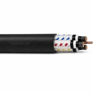
Mine Feeder Type 1 Screened Machine Cable 1.1/1.1 kV
A related cable option for a different application or duty profile.
View product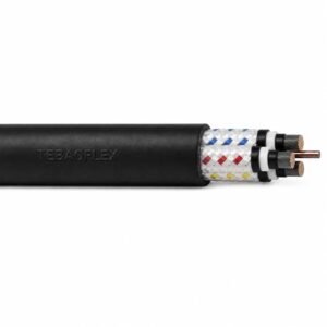
Mine Feeder Type 2S and Type 2S.3 Screened Machine Cable 1.1/1.1–3.3/3.3 kV
A related cable option for a different application or duty profile.
View product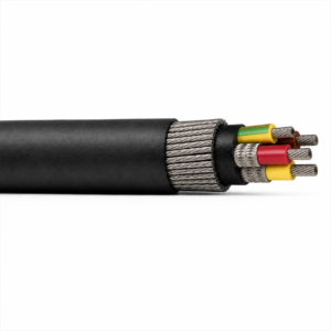
Type 201 / Type 211 BS 6708 640/1100 V Armoured Trailing Cable
A related cable option for a different application or duty profile.
View productRequest a cable recommendation and quotation
Send the required services, cable length, mechanical duty, environment, termination and quantity. Our team will review the application before quoting.
- Include the product name or SKU plus the required cable length and quantity.
- Attach a specification, drawing or data sheet when available.