











Industrial Welding Cable 600 V–1 kV — EPDM, EPR, TPE and CPE
Flexible single-conductor industrial welding cable in 600 V and 0.6/1 kV constructions, with fine-stranded copper and material-specific EPDM, EPR, TPE, CPE, TSE or XLPE/TPE coverings. Select the construction, conductor size, welding duty cycle and complete circuit length for quotation.
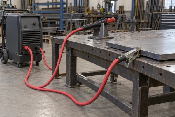
Industrial welding cable provides the flexible current path between welding equipment, an electrode holder or welding gun, and the work-return connection. This family covers separately specified 600 V constructions and 0.6/1 kV single-core power-and-welding constructions. Fine-stranded copper supplies the conductor flexibility; the selected insulation and covering determine the thermal and environmental duty.
Choose the material construction before comparing conductor sizes. The 600 V selection includes EPDM and EPR rubber, TPE, Class M copper with a CPE composite covering, and fabric-served TSE options. The 0.6/1 kV selection includes a distinct XLPE-insulated, TPE-sheathed build and a CPE composite single-core build. These options have separate dimensions and current tables so that an outer diameter or operating temperature remains attached to its actual construction.
Welding current is only one sizing input. Include the outward and return leads, the operating duty cycle, the allowed voltage drop, cable grouping and the route around the work area. A short intermittent electrode lead and a continuously loaded power connection can require different conductor sizes even when the welding set displays the same current. The Specifications section keeps continuous-duty values and five-minute welding-cycle values in their respective tables.
Use this page to select a construction and nominal size for a fabrication shop, maintenance welding lead, battery connection or documented flexible power circuit. Provide the cable length, current and duty cycle, voltage, termination drawing, jacket material and operating environment. For a moving robotic welding gun, use the dedicated robotic construction and assess the complete cable dress package.
Explore the welding cable range for related configurations.
For the effect of lead length and operating duty on conductor selection, see the welding cable sizing guide and retain the stated conditions for each current table.
Construction
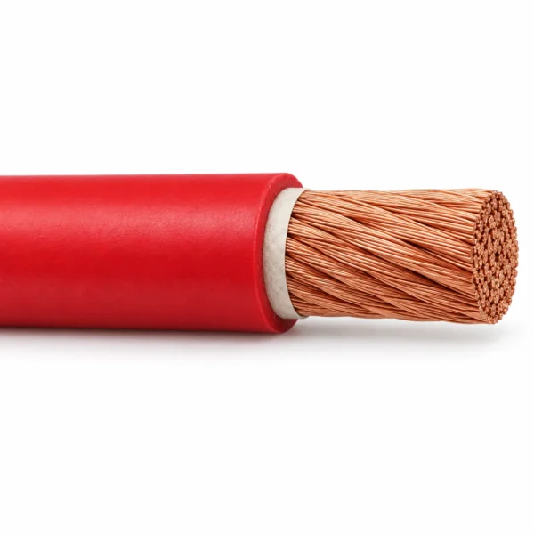
The representative red EPDM image is a single conductor made from fine bare copper wires, a thin paper separator and one EPDM composite insulation/jacket. Other material options below retain their own layer sequence; fabric serve and a separate XLPE insulation layer belong only to the constructions that specify them.

| Component | Material and construction |
|---|---|
| Copper conductor | Fine-stranded annealed bare copper. Class K and Class M constructions are identified separately; strand counts remain specific to each size table. |
| Separator | Paper or tape separator in the EPDM, EPR and Class M CPE builds that specify it, supporting stripping and separation from the covering. |
| Composite rubber or elastomer covering | EPDM, EPR, TPE or CPE construction as selected; a composite covering performs the documented insulation and outer-protection functions. |
| Fabric-served TSE option | Fine copper conductor with a full fabric serve impregnated into the TSE jacket; this reinforcement is textile and is not a metallic screen. |
| Separate XLPE/TPE option | Flexible copper with XLPE insulation and a separate TPE outer sheath for the listed 0.6/1 kV construction. |
| Core arrangement | One current-carrying conductor per cable. Electrode and work-return leads are separate circuit conductors; no copper shield, metallic armour or extra control core is shown in the representative EPDM image. |
Applications
Select industrial welding cable for the electrical circuit and its actual movement and environment. Route the leads to avoid hot workpieces, sharp edges, vehicle traffic and strain at the terminals.
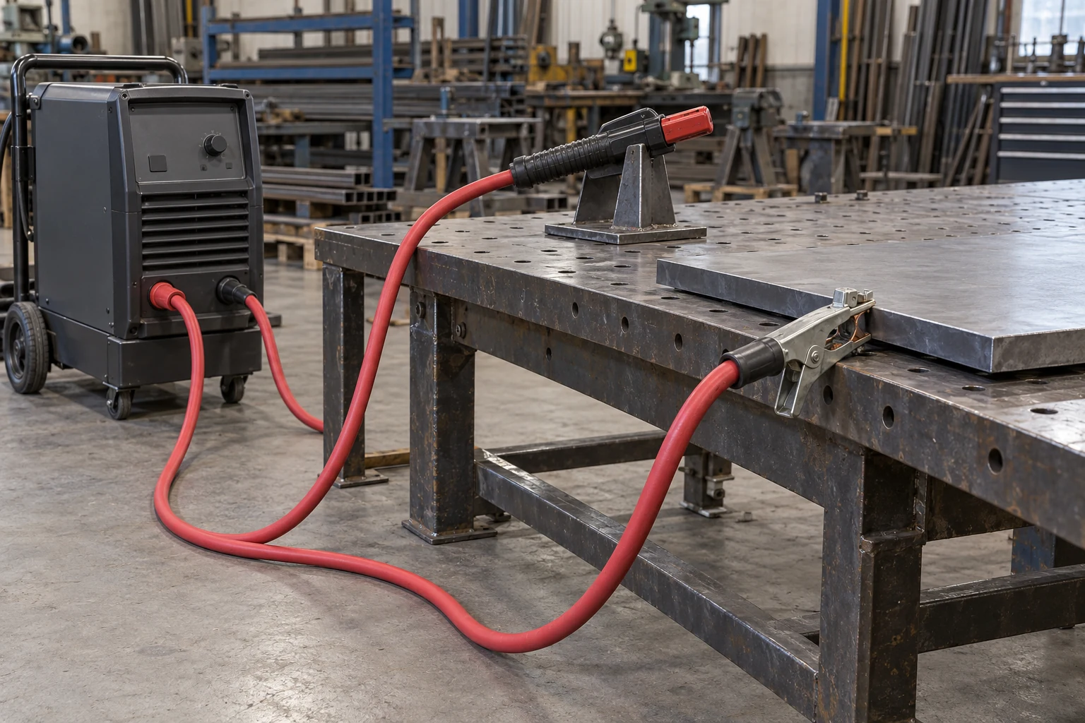
- Flexible electrode-holder, stinger and work-return leads in fabrication and maintenance welding.
- Secondary resistance-welding connections where the selected construction and current duty match the equipment.
- Battery, motor or generator connections when the chosen voltage rating and installation requirements permit the application.
- 0.6/1 kV single-core flexible connections to switchgear or other low-voltage equipment using the separate power-and-welding construction.
- Choose a dedicated robotic welding cable when the route follows repeated robot articulation; a flexible manual welding lead does not by itself establish a robot motion rating.
- Provide complete circuit length, duty cycle, ambient temperature, grouping, exposure to oils or chemicals, and terminal dimensions when selecting the lead.
Specifications
| Parameter | Value |
|---|---|
| Voltage constructions | 600 V; selected Class M CPE construction rated 600 V DC; separate power-and-welding constructions rated U₀/U 0.6/1 kV. |
| Conductor | Fine-stranded annealed bare copper; Class K, Class M and other documented strand arrangements listed separately. |
| Insulation and covering | EPDM, EPR, TPE, CPE, fabric-served TSE or separate XLPE/TPE, according to the selected construction. |
| Temperature selection | 90 °C or 105 °C maximum conductor temperature, depending on the material option; see the construction matrix. |
| Available size families | 8 AWG to 500 kcmil across the listed 600 V options; 10 mm² to 630 mm² across the separate 0.6/1 kV options. |
| Circuit configuration | Single conductor; select separate electrode and work-return lead lengths. |
| TSE bending reference | 6 × cable OD static; 8 × cable OD dynamic, for the fabric-served TSE construction only. |
| Current selection | Use the stated conductor temperature, ambient temperature, installation and duty-cycle basis for each table. |
| Construction option | Conductor | Insulation and covering | Temperature basis | Size range |
|---|---|---|---|---|
| 600 V EPDM Class K | Annealed bare copper; 30 AWG stranding | EPDM composite insulation/jacket | -50 °C to +105 °C | 6 AWG to 500 kcmil |
| 600 V heavy-jacket EPDM | Annealed bare copper; 30 AWG stranding | Thicker EPDM covering | -50 °C to +105 °C | 6 AWG to 4/0 AWG |
| 600 V compact EPDM | Bunch-stranded, rope-lay copper; 30 AWG stranding | Paper separator and EPDM covering | -50 °C to +105 °C | 8 AWG to 500 kcmil |
| 600 V EPR Class K | Bare copper to ASTM B172 Class K | Paper separator; 105 °C EPR Class 45 | -40 °C to +105 °C | 6 AWG to 500 kcmil |
| 600 V TPE 105 °C | Flexible soft copper | Black TPE insulation | 105 °C maximum conductor temperature | 6 AWG to 4/0 AWG |
| 600 V DC CPE Class M | Bare copper to ASTM B3 / ASTM B172 Class M | Paper separator; thermoset CPE composite insulation/jacket | 90 °C maximum conductor temperature | 4 AWG to 4/0 AWG |
| 600 V fabric-served TSE | Fine-stranded bare copper | 100% fabric serve impregnated into TSE jacket | 90 °C maximum conductor temperature | 6 AWG to 4/0 AWG |
| 0.6/1 kV XLPE/TPE | Flexible copper | XLPE insulation and separate TPE sheath | 90 °C continuous conductor temperature | 10 mm² to 630 mm² |
| 0.6/1 kV CPE single-core | Taped, multiple-stranded plain copper | CPE composite insulation and protection | 90 °C continuous conductor temperature | 10 mm² to 240 mm² |
| Cable configuration | Stranding (no./AWG) | OD (in) | OD (mm) | Approx. mass (lb/1000 ft) |
|---|---|---|---|---|
| EPDM Class K 6 AWG | 259/30 | 0.320 | 8.13 | 135 |
| EPDM Class K 4 AWG | 406/30 | 0.375 | 9.53 | 172 |
| EPDM Class K 2 AWG | 646/30 | 0.465 | 11.81 | 260 |
| EPDM Class K 1 AWG | 812/30 | 0.495 | 12.57 | 317 |
| EPDM Class K 1/0 AWG | 1025/30 | 0.560 | 14.22 | 400 |
| EPDM Class K 2/0 AWG | 1274/30 | 0.615 | 15.62 | 487 |
| EPDM Class K 3/0 AWG | 1613/30 | 0.670 | 17.02 | 605 |
| EPDM Class K 4/0 AWG | 2029/30 | 0.750 | 19.05 | 827 |
| EPDM Class K 250 kcmil | 2496/30 | 0.830 | 21.08 | 976 |
| EPDM Class K 350 kcmil | 3441/30 | 0.950 | 24.13 | 1338 |
| EPDM Class K 500 kcmil | 5054/30 | 1.200 | 30.48 | 1995 |
| Cable configuration | Stranding (no./AWG) | OD (in) | OD (mm) | Approx. mass (lb/1000 ft) |
|---|---|---|---|---|
| Heavy-jacket EPDM 6 AWG | 259/30 | 0.420 | 10.67 | 140 |
| Heavy-jacket EPDM 4 AWG | 416/30 | 0.475 | 12.07 | 200 |
| Heavy-jacket EPDM 2 AWG | 655/30 | 0.520 | 13.21 | 280 |
| Heavy-jacket EPDM 1 AWG | 827/30 | 0.575 | 14.61 | 350 |
| Heavy-jacket EPDM 1/0 AWG | 1042/30 | 0.600 | 15.24 | 415 |
| Heavy-jacket EPDM 2/0 AWG | 1316/30 | 0.645 | 16.38 | 510 |
| Heavy-jacket EPDM 3/0 AWG | 1660/30 | 0.715 | 18.16 | 620 |
| Heavy-jacket EPDM 4/0 AWG | 2062/30 | 0.765 | 19.43 | 760 |
| Cable configuration | Stranding (no./AWG) | Insulation thickness (mm) | OD (mm) | Approx. mass (lb/1000 ft) |
|---|---|---|---|---|
| Compact EPDM 8 AWG | 182/30 | 1.52 | 6.85 | 80 |
| Compact EPDM 6 AWG | 260/30 | 1.52 | 7.74 | 110 |
| Compact EPDM 4 AWG | 364/30 | 1.65 | 8.45 | 145 |
| Compact EPDM 2 AWG | 624/30 | 1.65 | 10.54 | 235 |
| Compact EPDM 1 AWG | 767/30 | 1.65 | 11.25 | 282 |
| Compact EPDM 1/0 AWG | 975/30 | 1.65 | 12.39 | 351 |
| Compact EPDM 2/0 AWG | 1196/30 | 1.65 | 13.36 | 423 |
| Compact EPDM 3/0 AWG | 1547/30 | 1.98 | 15.46 | 553 |
| Compact EPDM 4/0 AWG | 1950/30 | 1.98 | 17.11 | 685 |
| Compact EPDM 250 kcmil | 2432/30 | 1.98 | 19.40 | 846 |
| Compact EPDM 350 kcmil | 3330/30 | 2.41 | 23.06 | 1172 |
| Compact EPDM 500 kcmil | 4847/30 | 2.41 | 26.77 | 1663 |
| Cable configuration | Stranding (no./AWG) | Insulation thickness (mm) | OD (mm) | Approx. mass (kg/km) | Max. DC resistance at 20 °C (Ω/km) | 105 °C conductor / 40 °C air current (A) |
|---|---|---|---|---|---|---|
| EPR Class K 6 AWG | 253/30 | 1.52 | 8.0 | 163 | 1.38 | 133 |
| EPR Class K 4 AWG | 403/30 | 1.52 | 9.1 | 240 | 0.865 | 179 |
| EPR Class K 2 AWG | 636/30 | 1.52 | 10.7 | 360 | 0.549 | 237 |
| EPR Class K 1 AWG | 798/30 | 2.03 | 12.5 | 468 | 0.436 | 284 |
| EPR Class K 1/0 AWG | 1016/30 | 2.03 | 13.9 | 583 | 0.345 | 327 |
| EPR Class K 2/0 AWG | 1261/30 | 2.03 | 15.0 | 708 | 0.276 | 377 |
| EPR Class K 3/0 AWG | 1590/30 | 2.03 | 16.7 | 877 | 0.219 | 449 |
| EPR Class K 4/0 AWG | 2007/30 | 2.03 | 17.9 | 1082 | 0.173 | 514 |
| EPR Class K 250 kcmil | 2399/30 | 2.41 | 20.5 | 1361 | 0.147 | 577 |
| EPR Class K 350 kcmil | 3327/30 | 2.41 | 22.7 | 1770 | 0.106 | 719 |
| EPR Class K 500 kcmil | 4746/30 | 2.41 | 28.5 | 2579 | 0.0743 | 908 |
| Cable configuration | Area (mm²) | Insulation thickness (mm) | OD (mm) | Approx. mass (kg/km) | Max. DC resistance at 20 °C (Ω/km) | 100% duty current (A) | 85% duty current (A) |
|---|---|---|---|---|---|---|---|
| TPE 105 °C 6 AWG | 13.3 | 1.52 | 7.94 | 155.25 | 1.38 | 75.0 | 120 |
| TPE 105 °C 4 AWG | 21.2 | 1.52 | 9.11 | 231.5 | 0.865 | 95.0 | 164 |
| TPE 105 °C 2 AWG | 33.6 | 1.52 | 10.72 | 347.34 | 0.549 | 130.0 | 224 |
| TPE 105 °C 1/0 AWG | 53.5 | 2.03 | 13.72 | 551.2 | 0.345 | 170.0 | 306 |
| TPE 105 °C 2/0 AWG | 67.4 | 2.03 | 14.92 | 683.33 | 0.276 | 195.0 | 357 |
| TPE 105 °C 3/0 AWG | 85 | 2.03 | 16.25 | 861.92 | 0.219 | 225.0 | 410 |
| TPE 105 °C 4/0 AWG | 107 | 2.03 | 17.72 | 1041.88 | 0.174 | 260.0 | 487 |
| Cable configuration | Stranding (no./AWG) | OD (in) | OD (mm) | Approx. mass (kg/km) | 90 °C conductor / 30 °C air current (A) |
|---|---|---|---|---|---|
| CPE Class M 4 AWG | 1064/34 | 0.455 | 11.56 | 309 | 140 |
| CPE Class M 2 AWG | 1666/34 | 0.540 | 13.72 | 476 | 190 |
| CPE Class M 1 AWG | 2107/34 | 0.600 | 15.24 | 565 | 220 |
| CPE Class M 1/0 AWG | 2646/34 | 0.660 | 16.76 | 737 | 260 |
| CPE Class M 2/0 AWG | 3325/34 | 0.730 | 18.54 | 885 | 300 |
| CPE Class M 3/0 AWG | 4256/34 | 0.800 | 20.32 | 1139 | 350 |
| CPE Class M 4/0 AWG | 5320/34 | 0.870 | 22.10 | 1324 | 405 |
| Cable configuration | Stranding (no./AWG) | OD (in) | Jacket thickness (in) | Approx. mass (lb/1000 ft) | 90 °C conductor / 30 °C air current (A) |
|---|---|---|---|---|---|
| Fabric-served TSE 6 AWG | 660/34 | 0.370 | 0.080 | 132 | 105 |
| Fabric-served TSE 4 AWG | 1045/34 | 0.450 | 0.093 | 202 | 140 |
| Fabric-served TSE 2 AWG | 1634/34 | 0.540 | 0.103 | 305 | 190 |
| Fabric-served TSE 1/0 AWG | 2597/34 | 0.660 | 0.115 | 416 | 260 |
| Fabric-served TSE 2/0 AWG | 3300/34 | 0.700 | 0.115 | 558 | 300 |
| Fabric-served TSE 3/0 AWG | 4214/34 | 0.797 | 0.140 | 721 | 350 |
| Fabric-served TSE 4/0 AWG | 5225/34 | 0.900 | 0.158 | 906 | 405 |
| Cable configuration | Max. strand diameter (mm) | OD (mm) | Approx. mass (kg/100 m) |
|---|---|---|---|
| XLPE/TPE 0.6/1 kV 10 mm² | 0.21 | 8.5 | 14.0 |
| XLPE/TPE 0.6/1 kV 16 mm² | 0.21 | 9.8 | 20.2 |
| XLPE/TPE 0.6/1 kV 25 mm² | 0.21 | 11.3 | 29.7 |
| XLPE/TPE 0.6/1 kV 35 mm² | 0.21 | 12.6 | 39.5 |
| XLPE/TPE 0.6/1 kV 50 mm² | 0.31 | 14.2 | 53.6 |
| XLPE/TPE 0.6/1 kV 70 mm² | 0.31 | 16.2 | 74.4 |
| XLPE/TPE 0.6/1 kV 95 mm² | 0.31 | 18.3 | 99.3 |
| XLPE/TPE 0.6/1 kV 120 mm² | 0.51 | 20.7 | 125 |
| XLPE/TPE 0.6/1 kV 150 mm² | 0.51 | 22.6 | 150 |
| XLPE/TPE 0.6/1 kV 185 mm² | 0.51 | 24.6 | 179 |
| XLPE/TPE 0.6/1 kV 240 mm² | 0.51 | 27.7 | 240 |
| XLPE/TPE 0.6/1 kV 300 mm² | 0.51 | 31.0 | 290 |
| XLPE/TPE 0.6/1 kV 400 mm² | 0.51 | 35.4 | 389 |
| XLPE/TPE 0.6/1 kV 500 mm² | 0.51 | 40.0 | 498 |
| XLPE/TPE 0.6/1 kV 630 mm² | 0.51 | 44.0 | 629 |
| Cable configuration | Max. strand diameter (mm) | Conductor diameter (mm) | Insulation/protection thickness (mm) | OD (mm) |
|---|---|---|---|---|
| CPE 0.6/1 kV 10 mm² | 0.21 | 4.5 | 2.0 | 8.9 |
| CPE 0.6/1 kV 16 mm² | 0.21 | 5.7 | 2.0 | 10.1 |
| CPE 0.6/1 kV 25 mm² | 0.21 | 6.5 | 2.0 | 10.9 |
| CPE 0.6/1 kV 35 mm² | 0.21 | 7.8 | 2.0 | 12.2 |
| CPE 0.6/1 kV 50 mm² | 0.21 | 9.6 | 2.2 | 14.4 |
| CPE 0.6/1 kV 70 mm² | 0.21 | 11.7 | 2.4 | 16.9 |
| CPE 0.6/1 kV 95 mm² | 0.21 | 13.7 | 2.6 | 19.4 |
| CPE 0.6/1 kV 120 mm² | 0.51 | 15.2 | 2.8 | 21.3 |
| CPE 0.6/1 kV 150 mm² | 0.51 | 16.5 | 3.0 | 23.1 |
| CPE 0.6/1 kV 185 mm² | 0.51 | 19.4 | 3.2 | 26.4 |
| CPE 0.6/1 kV 240 mm² | 0.51 | 22.9 | 3.4 | 30.3 |
| Conductor configuration | 100% continuous (A) | 60% heavy duty (A) | 30% light industrial (A) | 25% limited input (A) |
|---|---|---|---|---|
| Welding single-core 10 mm² | 90 | 96 | 114 | 121 |
| Welding single-core 16 mm² | 125 | 137 | 169 | 181 |
| Welding single-core 25 mm² | 165 | 188 | 239 | 257 |
| Welding single-core 35 mm² | 205 | 238 | 309 | 334 |
| Welding single-core 50 mm² | 260 | 308 | 407 | 440 |
| Welding single-core 70 mm² | 325 | 391 | 523 | 567 |
| Welding single-core 95 mm² | 390 | 476 | 644 | 700 |
| Welding single-core 120 mm² | 455 | 559 | 762 | 829 |
| Welding single-core 150 mm² | 535 | 661 | 904 | 985 |
| Welding single-core 185 mm² | 600 | 747 | 1027 | 1120 |
| Welding single-core 240 mm² | 715 | 895 | 1236 | 1348 |
| Cable configuration | Portable in-line current (A) |
|---|---|
| EPDM Class K 6 AWG | 75 |
| EPDM Class K 4 AWG | 100 |
| EPDM Class K 2 AWG | 140 |
| EPDM Class K 1 AWG | 160 |
| EPDM Class K 1/0 AWG | 190 |
| EPDM Class K 2/0 AWG | 223 |
| EPDM Class K 3/0 AWG | 265 |
| EPDM Class K 4/0 AWG | 310 |
| EPDM Class K 250 kcmil | 445 |
| EPDM Class K 350 kcmil | 552 |
| EPDM Class K 500 kcmil | 695 |
All listed dimensions and masses are nominal. Match the material option, strand arrangement, colour and termination drawing before fixing a cable-entry or lug size. AWG and kcmil ordering sizes are retained as stated; the metric area column is included only where that construction provides it.
The EPR Class K current column applies in free air at 105 °C conductor temperature and 40 °C ambient temperature in continuous duty. The separate TPE 105 °C table uses 90 °C conductor temperature and 30 °C ambient: the 100% column follows NTC 6078 Table B.5 for up to three loaded conductors in conduit or directly buried; the 85% column follows Table B.4 for repeated five-minute work cycles.
CPE Class M and fabric-served TSE current figures use continuous duty at 30 °C ambient and 90 °C conductor temperature. The EPDM Class K in-line table uses continuous portable-cable duty at 40 °C ambient. These figures are distinct from the 0.6/1 kV welding table with 100%, 60%, 30% and 25% duty over a five-minute cycle.
For secondary welding leads, include the electrode and work-return lengths in the voltage-drop assessment. A per-lead distance and a total-circuit distance are different sizing inputs; specify which distance is supplied with the enquiry.
Black and red EPR sizes share the listed electrical construction from 6 AWG through 4/0 AWG; 250–500 kcmil rows are the black EPR option. TSE colour options share the listed size construction; select yellow, black or red where available for the required size.
The 0.6/1 kV power-and-welding tables describe the stated 90 °C XLPE/TPE and CPE constructions. Their ratings and dimensions remain separate from higher-temperature or halogen-free compounds selected for a different design.
Standards
| Standard or specification | Application |
|---|---|
| ASTM B3 / ASTM B172 | Soft or annealed copper and rope-lay stranded copper references for the specified Class K or Class M constructions. |
| UL 62 / UL 1276 | Conductor and 600 V welding-cable construction references for the Class M CPE option. |
| ANSI/NEMA WC58 / ICEA S-75-381 | Thermoset CPE composite insulation/jacket reference for the Class M construction. |
| UL 1581, Table 50.55, Class 45 | 105 °C EPR compound reference for the EPR Class K option. |
| NTC 6078 | 600 V TPE welding-cable construction and the separately stated current-rating conditions. |
| NTC 3203 No. 1080 / VW-1 | Flame-test references listed for the 600 V TPE construction. |
| CSA FT-1 / FT-5 | Flame-test references for the Class M CPE construction; the fabric-served TSE option lists FT-1. |
| AS/NZS 5000.1 / AS/NZS 1995 | Power and welding construction references for the listed 0.6/1 kV XLPE/TPE and CPE options. |
| AS 1966 | Duty-cycle reference used by the separate five-minute 0.6/1 kV welding current table. |
| SAE J1127 | Construction reference for the compact EPDM option from 6 AWG through 250 kcmil. |
Related cable options
Compare these cable options by service combination, movement, load, voltage and transmission requirement.
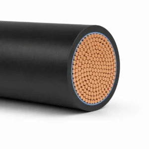
WCT Welding Cable for Arc Welder Secondary Leads
A related cable option for a different application or duty profile.
View product
H01N2-D / H01N2-E Welding Cable 100/100 V
A related cable option for a different application or duty profile.
View product
Robotic Welding Cable 600 V DC for Articulated Welding Guns
A related cable option for a different application or duty profile.
View productRequest a cable recommendation and quotation
Send the required services, cable length, mechanical duty, environment, termination and quantity. Our team will review the application before quoting.
- Include the product name or SKU plus the required cable length and quantity.
- Attach a specification, drawing or data sheet when available.