


WCT Welding Cable for Arc Welder Secondary Leads
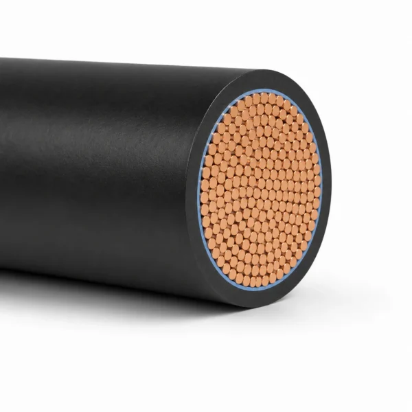
WCT welding cable is a natural-rubber-sheathed, single-conductor cable for the secondary-side connection of arc welders. Its supplied construction uses a stranded bare or tinned annealed copper conductor, a separator and a natural rubber compound sheath.
- Model: WCT
- Application: arc-welder secondary leads
- Conductor: stranded bare or tinned annealed copper
- Separator: suitable separator over the conductor
- Sheath: natural rubber compound
- Withstand test: 1,000 V for 1 minute in water; this is a test value, not a rated voltage
- References: JIS C 3005, JIS C 3102, JIS C 3152 and JIS C 3404
Send the conductor size, maximum welding current, duty cycle, total length, terminal details and documentation requirements for technical review.
WCT Welding Cable for Arc Welder Secondary Leads
WCT welding cable is a flexible single-conductor cable for the secondary-side connection of arc-welding equipment. Its supplied construction uses a stranded bare or tinned annealed copper conductor, a separator and a natural-rubber compound sheath. It is the appropriate search and quotation route when a drawing, replacement lead or procurement schedule specifically calls for WCT or JIS C 3404 welding cable.
Select conductor area from maximum welding current, duty cycle, total outgoing-and-return circuit length and acceptable voltage drop. Longer leads add resistance, while tightly coiled cable can retain heat. The supplied 1,000 V for 1 minute value is a dielectric withstand test, not evidence that WCT is rated for 1 kV operation.
- Typical use: arc-welder secondary leads and verified WCT replacements.
- Confirm before ordering: nominal area, current, duty cycle, total length, terminal design and documentation.
- Do not assume: fixed-wiring, oil, flame, weathering or reeling suitability without project evidence.
Send a photo of existing sheath marking and both terminations for replacement work. Compare the European H01N2-D / H01N2-E welding cable or browse industrial cables; different standard families are not automatic substitutes.
Construction
The supplied WCT construction is a single stranded conductor with a separator and natural rubber compound sheath.
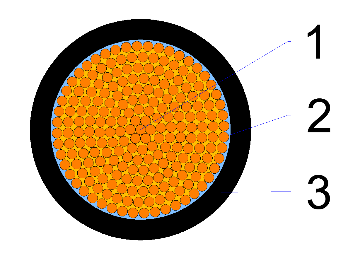
| 1. Conductor | Stranded annealed copper wire: bare copper referenced to JIS C 3102 or tinned copper referenced to JIS C 3152. |
|---|---|
| 2. Separator | A suitable separator is applied over the conductor. |
| 3. Sheath | Natural rubber compound. The source defines average and minimum thickness relative to an attached size table, but that table was not supplied. |
| Cable marking | Cable symbol, nominal cross-sectional area, and manufacturer name or abbreviation. |
Applications
WCT is intended for the conductor connection on the secondary side of arc welders where this natural-rubber-sheathed construction is specified.
- Secondary-circuit conductor connection for arc-welding equipment
- Replacement of an existing lead carrying a verified WCT marking
- Bare cable supply or termination to the buyer's confirmed lug or connector arrangement
Confirm current, duty cycle, total length and terminal capacity before selection. Do not use this page as evidence for primary power wiring, 1 kV-rated circuits, fixed building wiring, oil or flame exposure, outdoor weathering, or repeated reeling.
Specifications
The following characteristics are preserved from the supplied specification. Size-specific dimensions, resistance and length data are omitted because the referenced attached table was not supplied.
| Item | Supplied characteristic | Test method / note |
|---|---|---|
| Appearance | Smooth surface without flaws that affect use | JIS C 3005, 4.1 |
| Construction | According to the source's attached structure and size table | JIS C 3005, 4.3; attached table not supplied |
| Conductor resistance | Not more than the value in the source's attached table | JIS C 3005, 4.4; values not supplied |
| Dielectric withstand voltage in water | 1,000 V for 1 minute | JIS C 3005, 4.6(a); test value, not rated voltage |
| Sheath tensile strength | At least 14 MPa | JIS C 3005, 4.16 |
| Sheath elongation | At least 430% | JIS C 3005, 4.16 |
| Thermal ageing: sheath tensile strength | At least 50% of the value before heating | JIS C 3005, 4.17 |
| Thermal ageing: sheath elongation | At least 50% of the value before heating | JIS C 3005, 4.17 |
| Impact | No damage or cracking; broken component wires in the conductor do not exceed 30% | JIS C 3005, 4.28; periodic in-house characteristic in the supplied document |
Size cross-reference: AWG and mm²
WCT is a JIS C 3404 construction marked by nominal cross-sectional area in mm². North American projects usually specify welding cable in AWG. The two systems do not line up exactly, so this table gives the true AWG area and the nearest standard metric size separately.
| AWG size | True area (mm²) | Nearest standard metric size (mm²) | Ampacity |
|---|---|---|---|
| 6 AWG | 13.3 | 16 | — |
| 4 AWG | 21.1 | 25 | — |
| 2 AWG | 33.6 | 35 | 150 A |
| 1 AWG | 42.4 | 50 | 170 A |
| 1/0 AWG | 53.5 | 50 | 200 A |
| 2/0 AWG | 67.4 | 70 | 235 A |
| 3/0 AWG | 85.0 | 95 | 275 A |
| 4/0 AWG | 107.0 | 120 | 315 A |
Substitute upward, not downward. 4/0 AWG is 107 mm², which falls between the 95 and 120 mm² metric sizes. Supplying 95 mm² against a 4/0 specification is an undersize; 120 mm² is the safe substitution. The same applies at 3/0, where 85 mm² sits between 70 and 95.
IEC 60228 classifies conductors by resistance rather than by area, so a substitution that looks correct on cross-section can still fail a resistance requirement. Confirm the resistance limit for the destination standard before accepting an equivalent size.
Available sizes and the corresponding construction data are confirmed per order. Send the welder output, total circuit length and duty cycle to request a sizing review, and see the welding cable size chart guide for the method behind the ampacity column.
Standards
The supplied document references the following standards and statutory/technical frameworks. A reference is not, by itself, evidence of an approval or certificate for every size.
| Reference | Supplied role | Scope note |
|---|---|---|
| JIS C 3404 | Welding cable product reference | Confirm the required edition and size scope at quotation stage. |
| JIS C 3005 | Electrical wire and cable test methods | The supplied characteristics cite clauses 4.1, 4.3, 4.4, 4.6(a), 4.16, 4.17 and 4.28. |
| JIS C 3102 | Bare annealed copper conductor reference | Applies when the bare-conductor option is ordered. |
| JIS C 3152 | Tinned annealed copper conductor reference | Applies when the tinned-conductor option is ordered. |
| Electrical appliance and material safety law; technical standards for electrical installations | Listed as applicable references in the supplied document | No product approval number or certificate scope was supplied. |
Package marking is specified to include the cable symbol and nominal area, length, year of manufacture or lot number, and manufacturer name. Confirm inspection records, marking language, packing and any project-specific documentation with the RFQ.
Related cable options
Compare these cable options by service combination, movement, load, voltage and transmission requirement.
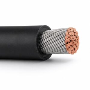
DLO Cable | 2 kV Diesel Locomotive Cable, 14 AWG–1111.1 kcmil
A related cable option for a different application or duty profile.
View product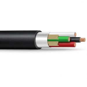
SOOW Cable 600V for Heavy-Duty Portable Power
A related cable option for a different application or duty profile.
View productRequest a cable recommendation and quotation
Send the required services, cable length, mechanical duty, environment, termination and quantity. Our team will review the application before quoting.
- Include the product name or SKU plus the required cable length and quantity.
- Attach a specification, drawing or data sheet when available.