










AS/NZS 1802 Type 245F and 241F Electro-Optic Mining Cable
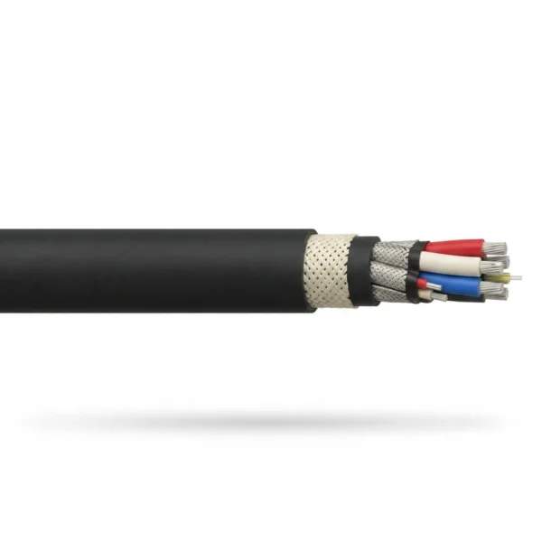
Three-core screened electro-optic trailing cable engineered to AS/NZS 1802 for automated underground coal longwall shearers, armored face conveyors (AFC), continuous miners and stacker-reclaimers at 1.1/1.1 kV and 1.9/3.3 kV. Combines three composite-screened R-EP-90 EPR power cores, pilot cores and an impact-protected 6 to 24 fibre optical unit inside a reinforced HD-85-PCP polychloroprene sheath.
Modern automated longwall faces, remote-controlled continuous miners and high-capacity rail-mounted stacker-reclaimers require simultaneous medium-voltage power delivery and interference-free optical data transmission inside a single trailing cable envelope. AS/NZS 1802 Type 245F and Type 241F electro-optic mining cables integrate three individually screened R-EP-90 EPR power cores, earth-continuity pilot conductors and a dedicated crush-resistant optical fibre assembly in one flexible round profile.
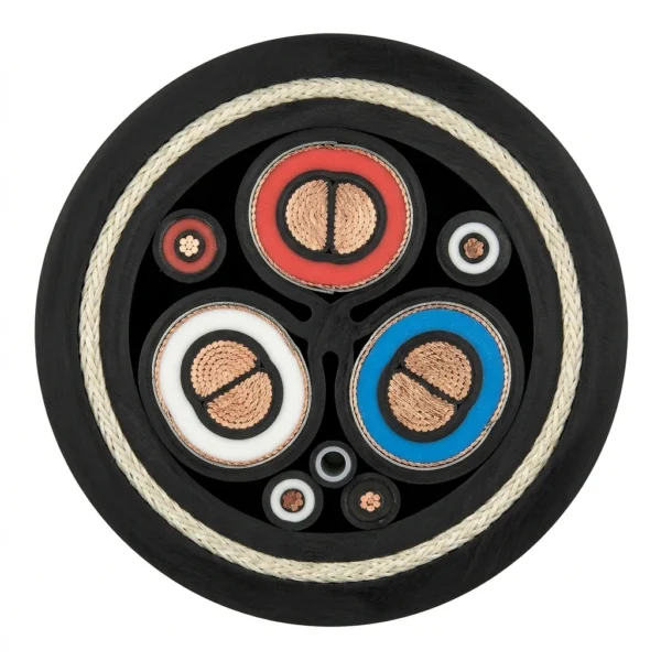
Understanding the structural distinction between Type 241F and Type 245F is essential when matching Australian and international underground coal mine protection philosophies. In Type 241F, each of the three semi-conducting screened power cores carries a helically braided tinned-copper and polyester composite earth screen that remains in mutual contact around the central elastomeric cradle. In Type 245F, each power-core composite screen is further enclosed within its own individual elastomeric barrier jacket, physically isolating the three phase earth screens to restrict inter-phase fault propagation in high-energy longwall face circuits.
The integrated fibre-optic sub-unit replaces one outer interstice filler or occupies a protected cradle channel, utilizing loose-tube or tight-buffered single-mode OS2 (ITU-T G.652.D) or multimode OM3/OM4 fibres reinforced with non-metallic aramid yarns and an elastomeric jacket. An open-weave polyamide anti-torsion braid embedded between the inner and outer heavy-duty HD-85-PCP polychloroprene sheaths prevents corkscrewing and axial fibre strain inside Bretby cable handler chains.
Explore the mining and tunneling cable range for related configurations.
AS/NZS 1802 Type 245F and 241F Construction
The representative horizontal sample illustrates the AS/NZS 1802 Type 245F 1.9/3.3 kV electro-optic construction, showing three flexible tinned copper power cores with triple-extruded semi-conducting screens and R-EP-90 EPR insulation, individually elastomeric-jacketed composite tinned-copper/polyester earth screens, two pilot cores, one reinforced optical fibre sub-unit in the third interstice, inner PCP bedding, open anti-torsion braid and heavy-duty HD-85-PCP outer sheath.
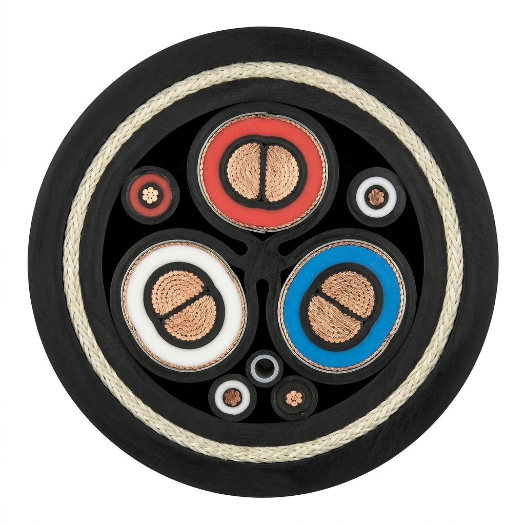
| Component | Material and construction |
|---|---|
| Power Conductors (3 x Class 5 Tinned Copper) | Flexible stranded annealed tinned copper conductors (16 mm2 to 240 mm2) complying with AS/NZS 1125 Class 5 for dynamic trailing and Bretby chain flexing. |
| Conductor Screen, EPR Insulation & Core Screen | Extruded semi-conducting elastomeric conductor screen, thermoset R-EP-90 ethylene propylene rubber (EPR) dielectric per AS/NZS 3808, and extruded semi-conducting insulation screen. |
| Composite Earth Screens (Type 241F vs Type 245F) | Tinned copper wire and polyester yarn composite braid over each power core providing collective earth fault capacity; Type 245F adds an individual elastomeric barrier sheath over each screened power core. |
| Pilot Conductors | One or two flexible tinned copper earth-continuity pilot cores insulated with R-EP-90 EPR laid in the outer interstices for pilot-circuit lockout monitoring. |
| Optical Fibre Element (F Designation) | Crush-resistant elastomeric-jacketed sub-unit reinforced with aramid strength yarns housing 6, 12 or 24 single-mode OS2 (G.652.D) or multimode OM3/OM4 optical fibres. |
| Central Cradle & Inner Bedding | Semi-conductive elastomeric central cradle profile and extruded HD-85-PCP inner sheath locking the laid-up cores against lateral migration. |
| Anti-Torsion Braid & HD-85-PCP Outer Sheath | Open-weave synthetic reinforcing braid vulcanized between the inner bedding and the extra-heavy-duty flame-retardant, oil- and abrasion-resistant HD-85-PCP polychloroprene outer sheath. |
AS/NZS 1802 Type 245F and 241F Code and Designation Breakdown
- AS/NZS 1802: Australian and New Zealand standard for reeling and trailing electric cables in underground coal mining applications
- Type 241F: Three R-EP-90 EPR power cores with unjacketed tinned-copper/polyester composite earth screens in mutual contact around a central cradle, plus pilots and optical fibre unit
- Type 245F: Three R-EP-90 EPR power cores where each composite phase earth screen is enclosed in an individual elastomeric barrier jacket, plus pilots and optical fibre unit
- 1.1/1.1 kV & 1.9/3.3 kV: Rated underground coal face AC voltages (1.2 kV and 3.6 kV maximum system voltages; 3.8/6.6 kV available on request)
- F (6/12/24F): Aramid-reinforced crush-resistant optical fibre sub-unit housing 6, 12 or 24 single-mode OS2 (ITU-T G.652.D) or multimode OM3/OM4 optical fibres
- HD-85-PCP: Extra-heavy-duty flame-retardant polychloroprene inner and outer sheath bonded across an open anti-torsion reinforcing braid
AS/NZS 1802 Type 245F and 241F Applications
Specify AS/NZS 1802 Type 245F and Type 241F electro-optic cables where mobile underground or surface mining machines demand combined power, earth-screen protection, pilot interlocking and high-speed optical telemetry.
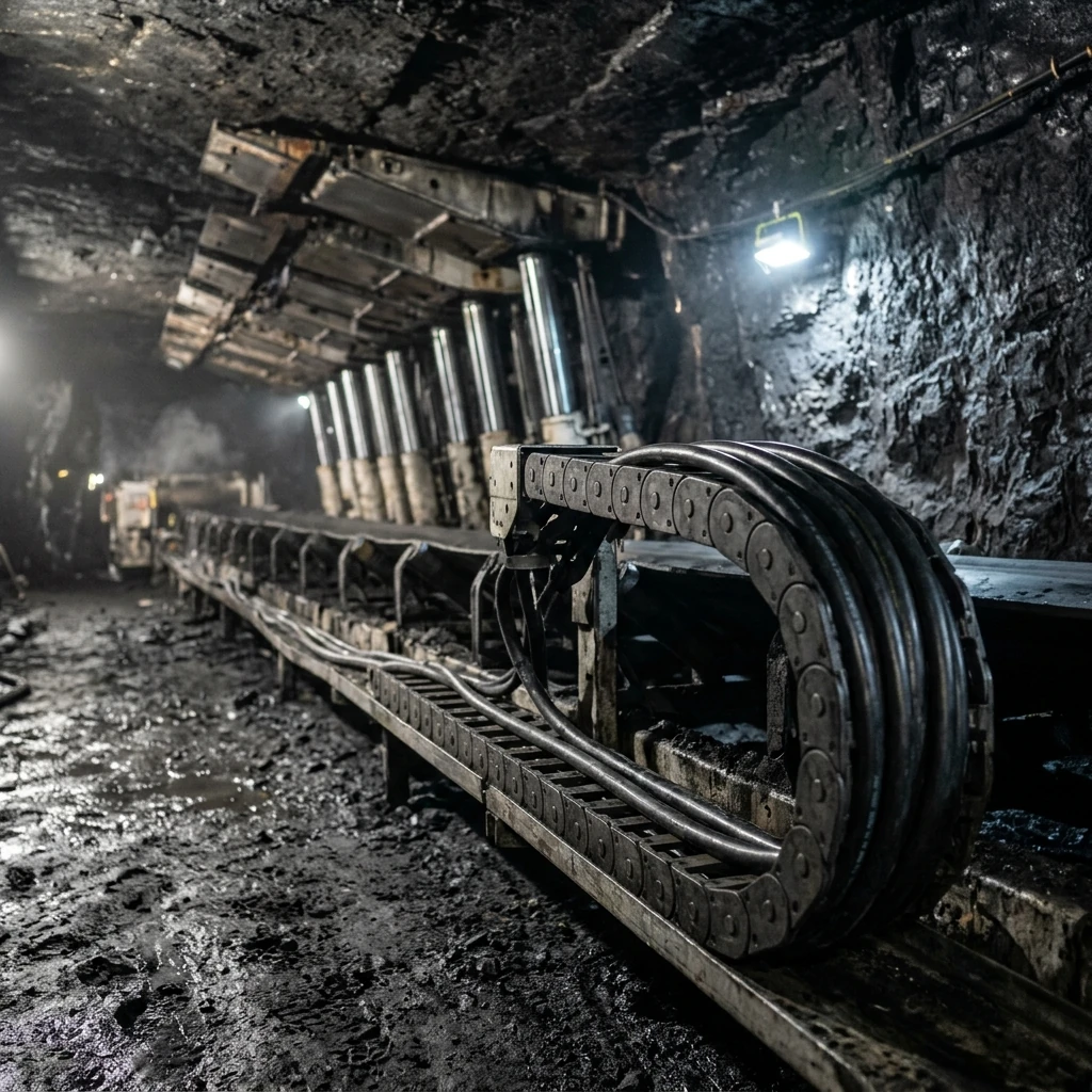
- Underground coal longwall shearers and armored face conveyors (AFC) operating inside Bretby automatic cable handler chains with real-time optical horizon-control and automation telemetry.
- Continuous miners, roadheaders and mobile bolting rigs requiring 1.1/1.1 kV or 1.9/3.3 kV trailing power paired with immune-to-EMI fiber optic video, lidar and gas-monitoring links.
- Open-cut and port bulk-handling stacker-reclaimers, ship loaders and mobile crushing stations where reeling or trailing cables carry both motor power and PLC fieldbus fiber.
- Direct engineering upgrades from standard non-optical Type 241 or Type 245 cables when retrofitting legacy mining machinery with fiber-optic diagnostics.
AS/NZS 1802 Type 245F and 241F Model Comparison and Selection Boundary
| Cable Designation | Standard | Rated Voltage Range | Phase Screen & Optical Construction | Primary Mining Application |
|---|---|---|---|---|
| Type 245F | AS/NZS 1802 | 1.1/1.1 kV & 1.9/3.3 kV (up to 6.6 kV) | Composite screen + individual elastomeric barrier over each phase + 6–24 fibres | High-energy automated underground coal longwall shearers and AFC Bretby chains |
| Type 241F | AS/NZS 1802 | 1.1/1.1 kV & 1.9/3.3 kV (up to 11 kV) | Unjacketed composite phase screens in mutual contact + 6–24 fibres | Underground continuous miners, roadheaders and compact electro-optic trailing runs |
| Type 245 / Type 241 | AS/NZS 1802 | 1.1/1.1 kV to 11/11 kV | Composite phase screens (barrier on 245), 3 interstitial copper pilots, no fibres | Standard underground coal trailing feeders without optical telemetry |
| Type 440F / Type 450F | AS/NZS 2802 | 3.3/3.3 kV to 33/33 kV | Surface Class 2 (440F) or Class 1 (450F) EPR wall + 6–24 fibres | Open-cut draglines, electric rope shovels, stacker-reclaimers and ship loaders |
Verify coupler gland entry bore before substituting Type 245F for Type 241F, as the individual elastomeric barrier sheath over each phase core increases nominal outside diameter by 1.6 mm to 3.2 mm.
Related selection resources
- Mining and tunneling cable engineering solutions
- AS/NZS 1802 and AS/NZS 2802 Australian mining cable selection guide
- AS/NZS 1802 Type 245 flexible rubber mining cable (1.1 to 6.6 kV)
- AS/NZS 1802 Type 241SF super-flexible mining cable (1.1 to 11 kV)
- 5kV to 15kV Mining VFD, VFD-GC and VFD-BGC Drive Cable
AS/NZS 1802 Type 245F and 241F Frequently Asked Questions
What is the structural difference between AS/NZS 1802 Type 241F and Type 245F electro-optic cables?
In Type 241F, the helically braided tinned-copper/polyester composite earth screens over the three R-EP-90 EPR power cores remain in direct mutual contact around the semi-conducting central cradle. In Type 245F, each power-core composite screen is enclosed within its own extruded elastomeric barrier jacket, isolating the three phase screens to limit inter-phase fault energy on longwall faces.
Which optical fibre grades and counts can be specified in Type 245F and Type 241F?
Both Type 245F and Type 241F can be built with 6, 12 or 24 optical fibres in single-mode OS2 (ITU-T G.652.D, 9/125 um) or laser-optimized multimode OM3 and OM4 (ISO/IEC 11801, 50/125 um) protected inside an aramid-reinforced elastomeric sub-unit.
Does the individual phase barrier on Type 245F affect mining plug and gland selection?
Yes. Because each screened power core in Type 245F carries an individual elastomeric barrier jacket, the nominal overall cable diameter is 1.6 mm to 3.2 mm larger than an equivalent Type 241F size; always confirm coupler gland bore dimensions before ordering.
What are the minimum order quantity and delivery lead time for Type 245F and Type 241F?
TEBAOFLEX manufactures custom continuous lengths of AS/NZS 1802 Type 245F and Type 241F from a 50 m minimum order quantity (MOQ) with a lead time of 7 to 45 working days, including routine high-voltage, partial-discharge and OTDR optical test reports.
AS/NZS 1802 Type 245F and 241F Technical Specifications
AS/NZS 1802 Type 245F and 241F Key Specifications
- Standard & Models: AS/NZS 1802:2003 Type 245F (individually barrier-jacketed phase screens) and Type 241F (unjacketed phase screens)
- Voltage Ratings: 1.1/1.1 kV (16–150 mm²) and 1.9/3.3 kV (25–240 mm²); 3.8/6.6 kV available on request
- Optical Fibre Sub-Unit: 6, 12 or 24 fibres in OS2 single-mode (9/125 um) or OM3/OM4 multimode (50/125 um) with aramid reinforcement
- Insulation & Sheath: R-EP-90 thermoset EPR insulation, composite tinned-copper/polyester earth screens and anti-torsion HD-85-PCP sheath
- Bend Radius & Supply: 6 x O.D. (Type 241F) / 8 x O.D. (Type 245F) min. dynamic bend radius; MOQ 50 m; lead time 7 to 45 working days
| Parameter | Value |
|---|---|
| Design standard reference | Engineered to AS/NZS 1802, AS/NZS 1125 and AS/NZS 3808 with ITU-T G.652.D or ISO/IEC 11801 optical fibres |
| Rated voltage classes | 1.1/1.1 kV (up to 1.2 kV max system) and 1.9/3.3 kV (up to 3.6 kV max system); 3.8/6.6 kV available on request |
| Type 241F vs Type 245F screen structure | Type 241F uses unjacketed composite screens in mutual contact; Type 245F encloses each phase screen in an elastomeric jacket |
| Continuous and short-circuit temperature | 90 C continuous conductor operating temperature and 250 C maximum short-circuit temperature (5 s max duration) |
| Minimum dynamic bending radius | 6 x overall cable diameter for Type 241F and 8 x overall cable diameter for Type 245F protecting internal optical fibres |
| Commercial supply terms | Minimum order quantity 50 m; manufacturing lead time 7 to 45 working days with factory routine electrical and OTDR optical test reports |
| Selection boundary vs Type 241 & Type 245 | Select Type 245F or 241F when integrated optical fibres are required; select standard Type 241 or Type 245 for copper-only power and pilot circuits. |
AS/NZS 1802 Type 241F & Type 245F 1.1/1.1 kV Size Schedule (16–150 mm²)
| Nominal Construction | Power Core Area (mm²) | Nominal Stranding (No./mm) | Nominal Insulation Thickness (mm) | Type 241F Nom. O.D. (mm) | Type 245F Nom. O.D. (mm) | Approx. Cable Mass (kg/km) | Current Rating at 30 °C Ambient (A) | Min. Dynamic Bend Radius 245F (mm) | Next step |
|---|---|---|---|---|---|---|---|---|---|
| 3x16 + 2P + 6/12F | 16 | 126/0.40 | 1.6 | 38.2 | 39.8 | 2150 | 105 | 235 | Request this size |
| 3x25 + 2P + 6/12F | 25 | 196/0.40 | 1.6 | 41.5 | 43.2 | 2780 | 135 | 255 | Request this size |
| 3x35 + 2P + 6/12F | 35 | 276/0.40 | 1.6 | 44.6 | 46.4 | 3420 | 165 | 280 | Request this size |
| 3x50 + 2P + 6/12F | 50 | 396/0.40 | 1.8 | 49.2 | 51.0 | 4390 | 200 | 305 | Request this size |
| 3x70 + 2P + 6/12F | 70 | 360/0.50 | 1.8 | 54.0 | 56.0 | 5580 | 245 | 335 | Request this size |
| 3x95 + 2P + 6/12F | 95 | 475/0.50 | 2.0 | 59.5 | 61.8 | 7120 | 295 | 370 | Request this size |
| 3x120 + 2P + 6/12F | 120 | 608/0.50 | 2.2 | 64.8 | 67.2 | 8640 | 340 | 405 | Request this size |
| 3x150 + 2P + 6/12F | 150 | 756/0.50 | 2.4 | 70.2 | 72.8 | 10350 | 390 | 440 | Request this size |
AS/NZS 1802 Type 241F & Type 245F 1.9/3.3 kV Size Schedule (25–240 mm²)
| Nominal Construction | Power Core Area (mm²) | Nominal Stranding (No./mm) | Nominal Insulation Thickness (mm) | Type 241F Nom. O.D. (mm) | Type 245F Nom. O.D. (mm) | Approx. Cable Mass (kg/km) | Current Rating at 30 °C Ambient (A) | Min. Dynamic Bend Radius 245F (mm) |
|---|---|---|---|---|---|---|---|---|
| 3x25 + 2P + 6/12F | 25 | 196/0.40 | 3.0 | 48.6 | 50.5 | 3490 | 140 | 305 |
| 3x35 + 2P + 6/12F | 35 | 276/0.40 | 3.0 | 51.8 | 53.8 | 4160 | 170 | 325 |
| 3x50 + 2P + 6/12F | 50 | 396/0.40 | 3.0 | 56.2 | 58.4 | 5180 | 205 | 350 |
| 3x70 + 2P + 6/12F | 70 | 360/0.50 | 3.0 | 60.8 | 63.2 | 6420 | 250 | 380 |
| 3x95 + 2P + 6/12F | 95 | 475/0.50 | 3.0 | 65.6 | 68.0 | 7980 | 300 | 410 |
| 3x120 + 2P + 6/12F | 120 | 608/0.50 | 3.0 | 70.4 | 73.0 | 9520 | 345 | 440 |
| 3x150 + 2P + 6/12F | 150 | 756/0.50 | 3.0 | 75.5 | 78.2 | 11290 | 395 | 470 |
| 3x185 + 2P + 6/12F | 185 | 925/0.50 | 3.0 | 80.6 | 83.5 | 13240 | 445 | 500 |
| 3x240 + 2P + 6/12F | 240 | 1221/0.50 | 3.0 | 87.4 | 90.6 | 16380 | 515 | 545 |
AS/NZS 1802 Type 245F & Type 241F Integrated Optical Fibre Sub-Unit Schedule
| Fibre Grade & Standard | Core / Cladding Diameter | Standard Fibre Counts | Max. Cabled Attenuation | Primary Mining Application |
|---|---|---|---|---|
| Single-Mode OS2 (ITU-T G.652.D) | 9 / 125 um | 6, 12 or 24 fibres | 0.38 / 0.25 dB/km (1310 / 1550 nm) | Longwall shearer automation, PLC telemetry and high-speed Gigabit Ethernet backbones |
| Multimode OM3 (ISO/IEC 11801) | 50 / 125 um laser-optimized | 6, 12 or 24 fibres | 3.0 / 1.0 dB/km (850 / 1300 nm) | Short-to-medium haul underground video monitoring, VFD drive sync and face sensors |
| Multimode OM4 (ISO/IEC 11801) | 50 / 125 um high-bandwidth | 6, 12 or 24 fibres | 3.0 / 1.0 dB/km (850 / 1300 nm) | High-bandwidth real-time coal-face lidar, thermal imaging and Bretby chain link telemetry |
Current-carrying capacities are referenced to 30 °C ambient air temperature and 90 °C maximum conductor operating temperature in free air away from direct solar radiation; apply AS/NZS 3008.1.1 derating factors where cables are layered in Bretby handlers, troughs or reels.
Type 245F nominal outside diameters are 1.6 mm to 3.2 mm larger than Type 241F of the same conductor cross-section due to the individual elastomeric barrier sheaths extruded over each composite phase screen; verify mining coupler gland entries before ordering.
Specify the exact fibre type (OS2 9/125 um, OM3 50/125 um or OM4 50/125 um), fibre count (6, 12 or 24 fibres) and whether one or two copper pilot cores are required alongside the optical unit.
ASCII part references for BOM and ERP entry: Type 245F 3x16+2P+6/12F, Type 245F 3x25+2P+6/12F, Type 245F 3x35+2P+6/12F, Type 245F 3x50+2P+6/12F, Type 245F 3x70+2P+6/12F, Type 245F 3x95+2P+6/12F, Type 245F 3x120+2P+6/12F, Type 245F 3x150+2P+6/12F, Type 245F 3x185+2P+6/12F, Type 245F 3x240+2P+6/12F, Type 241F 3x25+2P+6/12F, Type 241F 3x50+2P+6/12F, Type 241F 3x95+2P+6/12F.
AS/NZS 1802 Type 245F and 241F Standards and Test References
| Standard or specification | Application |
|---|---|
| AS/NZS 1802:2003 | Electric cables — Reeling and trailing — For underground coal mining applications (core construction basis for Type 241 and Type 245 with integrated optical unit F). |
| AS/NZS 1125 & AS/NZS 3808 | Flexible tinned copper Class 5 conductor stranding and R-EP-90 / HD-85-PCP insulating and sheathing elastomer compound specifications. |
| ITU-T G.652.D & IEC 60794 | Single-mode and multimode optical fibre transmission, micro-bending attenuation and mechanical crush/cyclic flexing performance. |
| AS/NZS 1660.5.6 & IEC 60332-1-2 | Vertical flame propagation resistance, oil immersion resistance and anti-static / flame-retardant outer sheath testing. |
Certifications and document support
TEBAOFLEX company certificates and quality system documentation
Standards New Zealand / AS/NZS 1802 Underground Coal Mining Reeling and Trailing Cable Scope
IEC Webstore — IEC 60794 Optical Fibre Cables and IEC 60228 Conductors
Related cable options
Compare these cable options by service combination, movement, load, voltage and transmission requirement.
Type 241.1 Mining Cable 1.1 kV | Type 241 Family
A related cable option for a different application or duty profile.
View product
Type 241SF Flexible Mining Cable 1.1/1.1–11/11 kV
A related cable option for a different application or duty profile.
View product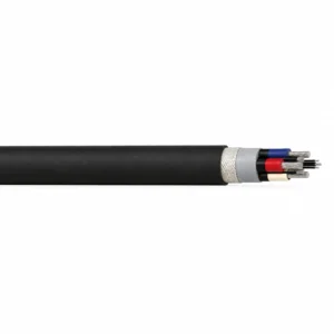
Type 245UF Ultra-Flexible Mining Cable 1.1–3.3 kV
A related cable option for a different application or duty profile.
View productRequest a cable recommendation and quotation
Send the required services, cable length, mechanical duty, environment, termination and quantity. Our team will review the application before quoting.
- Include the product name or SKU plus the required cable length and quantity.
- Attach a specification, drawing or data sheet when available.