









ISO 6858:2017, ISO 461 & airport ground support engineering guide
Specifying a 400 Hz pit cable vs GPU cable requires separating three distinct airport mechanical duties rather than ordering one generic aircraft lead: underground apron pit hatch systems use four twisted, individually PUR-sheathed cores (such as 4 × (1×70 + 4×1 mm²)) with no overall jacket for meltwater drainage and −40 °C hand flexibility; mobile GPU carts and motorized drum retrievers require a round overall-sheathed 7-core symmetrical concentric cable (6×35 mm² phases around a central neutral) for smooth coiling and low 400 Hz reactance; and passenger boarding bridges pair fixed LSOH terminal feeders with ultra-flexible Class 6 drag-chain and boom output assemblies.
Why can’t one 400 Hz ground power cable serve apron pits, mobile GPU reels and boarding bridges?
Under ISO 6858:2017 (Aircraft ground support electrical supplies), every 90 kVA fixed electric ground power (FEGP) or mobile ground power unit (GPU) circuit must deliver 115/200 V three-phase AC at 400 Hz within 115 V ± 3 V at the aircraft receptacle, while surviving three incompatible mechanical environments—flooded underground concrete vaults, high-tension motorized reel drums, and enclosed terminal walkways.
At 400 Hz, inductive reactance (XL = 2πfL) is eight times higher than at 50 Hz, dominating voltage drop on 70 mm² to 120 mm² conductors (the full reactance and line-drop compensation formulas are derived in our 400 Hz ground power cable voltage drop calculation guide). Solving 400 Hz reactance while surviving apron handling forces engineers to choose among four distinct cable architectures rather than one universal construction.
How do 4-bundle pit cables, 7-core GPU reel cables, bridge boom cables and fixed feeders compare?
Under ISO 6858:2017 airport ground power engineering practice, four 115/200 V 400 Hz cable architectures divide strictly by mounting environment: open four-bundle PUR twists serve flooded underground apron pits (15 to 28 m), round 7-core concentric PUR cables serve motorized GPU drums (20 to 45 m), Class 6 round PUR cables serve boarding-bridge booms, and LSOH quad/concentric feeders serve fixed terminal corridors.
| 400 Hz architecture | Typical core geometry | Outer profile & sheath | Standard run length | Choose this when |
|---|---|---|---|---|
| Apron pit 4-bundle twist | 4 × (1×70 + 4×1 mm²) separately sheathed | Open 4-core twist · Yellow/orange PUR per core (no overall jacket) | 15 m (narrow-body) to 28 m (wide-body) | Pop-up or hatch apron pits exposed to snowmelt, runway de-icer and manual ramp pulling down to −40 °C |
| 7-core concentric GPU / retriever | 6 × 35 mm² (split phases) + central N + 12–24 × 1.0/1.5 mm² | True round · Heavy abrasion-resistant PUR outer sheath | 20 m to 45 m on drum or motorized retriever | Diesel/electric mobile GPU trailers, horizontal/vertical motorized drum retrievers and pantograph reels |
| 4-core round bridge / drag-chain | 4 × 50/70 mm² + interstitial control bundles (Class 6 Cu) | Round · High-visibility orange/yellow PUR | 12 m to 30 m boom / telescoping chain span | Passenger boarding bridge (PBB) articulating energy chains, alligator booms and short hand-coiled drops |
| Symmetrical fixed 400 Hz feeder | Quad / 7-core concentric 70–120 mm² per phase + sense pairs | Round fixed · Flame-retardant LSOH / FRNC | 40 m to 250 m converter-to-gate run | Central 400 Hz inverter room to PBB rotunda or apron pit vault where low reactance and indoor fire codes apply |
Why do underground apron pit systems specify 4 × (1×70 + 4×1 mm²) open bundles cut to 15 m and 28 m?
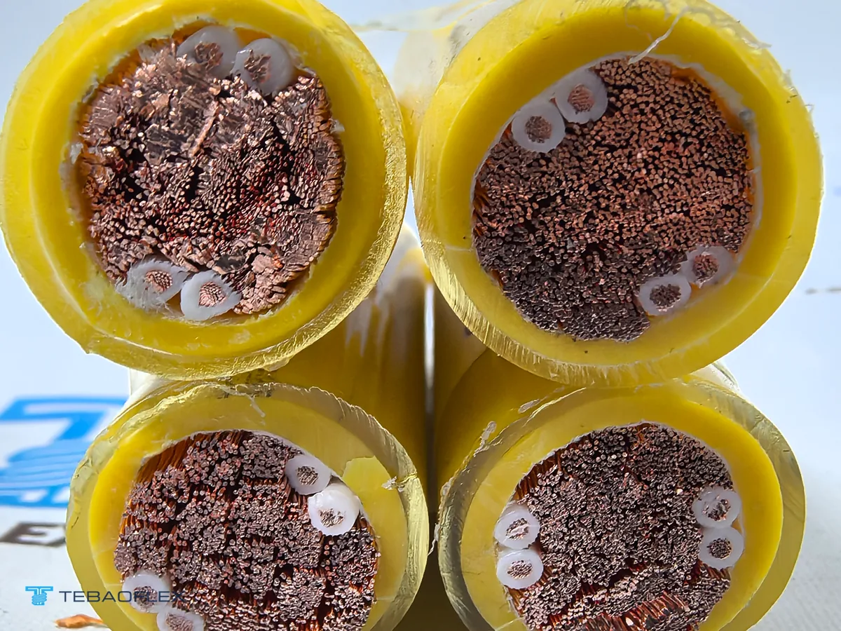
Underground airport pit vaults accumulate rainwater, melted snow, Jet A-1 spills and potassium-formate runway de-icer while storing coiled cable in tight subterranean chambers. Twisting four separately PUR-sheathed 70 mm² cores together without an outer jacket prevents trapped water pockets from freezing and splitting an outer sheath, while letting each sub-cable slide slightly during tight manual coiling.
Our 2026 production record for a 450 m Russian civil airport 400 Hz pit system order (4 × (1×70 + 4×1 mm²)) illustrates three engineering details buyers confirm on pit replacements:
- Four self-contained sub-cables (16 total pilot cores): Each of the four yellow PUR-sheathed cores contains one 70 mm² IEC 60228 Class 5 tinned-copper conductor plus four 1 mm² Class 6 grey FEP-insulated control cores under black cross-linked EPR bedding, printed externally with core numbers 1 to 4 and metre marks. Distributing four 1 mm² pilots into every core keeps all four sub-cables identical in diameter and pitch symmetry while providing redundant E/F interlock and sense circuits.
- Why buyers cut 450 m bulk drums into 15 m and 28 m assemblies: Rather than installing 50 m leads that waste pit vault volume and add unnecessary 400 Hz inductive voltage drop, aviation equipment assemblers cut 15 m leads for narrow-body stands (A320 / B737 single-plug 90 kVA) and 28 m leads for wide-body nose-gear reach (B777 / A350 dual-plug 2 × 90 kVA), fitting 6-pole 400 Hz aircraft plugs locally.
Why must mobile GPU drums and motorized cable retrievers use round 7-core concentric 6×35 mm² cables?
Motorized drum retrievers, vertical coil retrievers and mobile diesel/battery GPU trailers pull cable over guide rollers under spring or torque-motor tension. An un-jacketed 4-bundle pit twist snags roller flanges and wedges between drum wraps; mobile reels require a smooth circular outer PUR sheath combined with a 7-core symmetrical concentric conductor geometry.
Inside a 7-core 400 Hz reeling cable—detailed on our 7-core 400 Hz aircraft ground power cable page, 400 Hz GPU reel Tripleflex cable schedule and 400 Hz motorized drum retriever cable specification—six 35 mm² phase conductors revolve around one central neutral conductor (typically 35 mm² to 50 mm²):
- Magnetic flux cancellation halves 400 Hz reactance: Pairing diametrically opposite 35 mm² cores on the same phase (L1 opposite L1, L2 opposite L2, L3 opposite L3 = 70 mm² per phase) interleaves forward and return phase magnetic fields, cutting 400 Hz inductive reactance to roughly 0.045–0.055 Ω/km compared with ~0.095–0.115 Ω/km on conventional four-core layouts.
- Balanced bending stiffness on compact retriever drums: Six 35 mm² Class 5 or Class 6 conductors bend far more easily around compact 300 to 400 mm GPU retriever barrels than four monolithic 70 mm² or 95 mm² cores, extending flex life across thousands of aircraft turnarounds.

How should passenger boarding bridge (PBB) fixed feeders be separated from moving drag-chain and boom cables?
A gate-mounted fixed electric ground power (FEGP) installation spans two completely different fire and motion zones between a central 400 Hz solid-state frequency converter and the aircraft nose receptacle—requiring two matched cable types rather than pulling apron PUR cable inside terminal ceilings:
- Zone 1 — Fixed terminal & rotunda feeder (40 to 250 m): When a central 400 Hz converter feeds gates across terminal cable trays, specify our low-reactance LSOH 400 Hz fixed feeder cable, symmetrical 400 Hz distribution cable or FRNC-quadroflex 400 Hz cable. Low-smoke zero-halogen compounds meet terminal fire regulations while symmetrical phase splitting preserves voltage regulation ahead of the bridge head.
- Zone 2 — Articulating PBB drag chain & aircraft drop (12 to 30 m): Through the telescoping boarding-bridge energy chain and under-bridge swivel boom, transition at a junction box to ultra-flexible Class 6 copper (compared in our Class 5 vs Class 6 conductor stranding guide) inside high-visibility orange or yellow apron PUR—see our 400 Hz aircraft ground power cable overview.
- Regional 28 V DC & static bonding companions: Gates serving turboprops, regional jets or helicopters alongside commercial airliners add a dedicated 28 V DC aircraft ground power cable and high-visibility aircraft static grounding cable.

What do the 28 V DC E/F interlock cores do, and why pair FEP pilot insulation with −40 °C PUR sheathing?
Under ISO 6858 and ISO 461 6-pole aircraft plug specifications, pins E and F carry a 28 V DC safety interlock loop that prevents live arc-flash disconnection, requiring thin-wall FEP fluoropolymer pilot insulation inside cold-flexible (−40 °C) Jet A-1- and de-icer-resistant polyurethane (PUR) outer sheathing to survive daily apron crush and winter ramp handling.
- FEP fluoropolymer insulation on 1.0–1.5 mm² E/F interlock & LDC sense cores: On standard ISO 461 6-pole aircraft plugs, shorter pilot pins E and F carry a 28 V DC interlock loop that confirms full plug seating before closing the 115/200 V contactor and drops power first on extraction. Extruding tough, thin-wall fluorinated ethylene propylene (FEP) over Class 6 tinned copper prevents pilot core pinch-through against heavy 70 mm² power cores when aircraft tug wheels or ramp boots compress the cable, and resists heat shrink or crimp/solder rework inside plug backshells.
- Aviation-grade polyether/ester PUR down to −40 °C flexing: Ordinary PVC or standard polychloroprene stiffens into coil memory on −30 °C to −40 °C winter aprons and swells when soaked in Jet A-1 kerosene, Skydrol phosphate-ester hydraulic fluid or runway de-icers. Specifying cold-climate aviation PUR (−40 °C dynamic flexing, −50 °C fixed) keeps pit and GPU assemblies supple without surface crazing.
Pre-RFQ specification checklist for airport 400 Hz and 28 V DC ground power cables
Sharing seven operational details at inquiry stage lets TEBAOFLEX match core symmetry, pilot count and cut-length voltage drop to your converter and aircraft stands.
- Apron duty & mounting mechanism: Underground hatch/pop-up pit (4-bundle twist), mobile GPU cart or motorized drum/coil retriever (round 7-core concentric), telescoping PBB drag chain, or fixed indoor LSOH terminal feeder.
- System power & aircraft plug standard: 115/200 V AC 400 Hz (90 kVA single plug or 2 × 90 kVA wide-body) per ISO 6858 / ISO 461, or 28 V DC continuous/peak start rating.
- Phase, neutral & pilot core configuration: 4 × 70 mm², 6 × 35 mm² + N, 4 × 95 mm² or customfeeder mm², plus total pilot/sense wire count (e.g. 4 × 4 × 1 mm² = 16 wires, or 12–24 × 1.0/1.5 mm²).
- Cut assembly lengths vs bulk drum length: Exact cut lengths (such as 15 m and 28 m) vs continuous bulk drum length (e.g. 450 m or 500 m), and converter LDC compensation limit.
- Connector supply scope: Cable only on sealed wooden drums, or 400 Hz / 28 V DC aircraft plugs supplied loose for buyer fitting vs factory-molded/fitted assemblies.
- Climate & jacket visibility: Minimum dynamic apron temperature (e.g. −40 °C), indoor LSOH fire requirement if inside terminals, and outer PUR color (high-visibility yellow, aviation orange or black).
- Marking & delivery schedule: Core numbering (1–4 or phase/pilot codes), metre marking and destination port.
As of November 2026, TEBAOFLEX manufactures custom 400 Hz and 28 V DC airport ground power cables at our Taicang facility from a 50 m minimum order quantity (MOQ), with standard production lead times of 7 to 45 working days depending on conductor lay-up and connector scope. Compare gate and apron layouts on our airport ground power cable solutions hub, browse all constructions in our airport ground power cables catalogue, or send your pit, GPU reel or boarding-bridge cable specification for engineering review.
Frequently asked questions
Why do underground airport pit systems use four twisted single-core bundles instead of one overall-jacketed cable?
In apron pop-up and hatch pit systems—such as a 4 × (1×70 + 4×1 mm²) construction—twisting four individually PUR-sheathed cores together without an overall outer jacket lets rain, snowmelt and glycol de-icing fluid drain freely between cores rather than pooling or freezing inside an outer sheath, while cutting hand-bending stiffness when ramp crews pull 15 m or 28 m leads up to parked aircraft at −40 °C.
Why do mobile GPU reels and motorized cable retrievers specify 7-core concentric 400 Hz cables instead of 4-core cables?
At 400 Hz, inductive reactance is eight times higher than at 50 Hz. Splitting each 70 mm² phase into two diametrically opposed 35 mm² sub-conductors (6 × 35 mm² arranged L1-L2-L3-L1-L2-L3 around a central neutral core inside one round PUR outer sheath) cancels magnetic flux to cut loop reactance roughly in half while maintaining a smooth circular profile that winds evenly onto motorized GPU drums and under-bridge retrievers.
Why are airport pit and bridge output assemblies commonly cut to 15 m, 22 m or 28 m rather than 60 m?
Under ISO 6858:2017, steady-state voltage at the aircraft service receptacle must stay within 115 V ± 3 V line-to-neutral at 400 Hz. Even low-reactance 70 mm² or 6×35 mm² flexible cables drop several volts over 30 m at 200–260 A aircraft load; pre-cutting apron pit leads to 15 m (narrow-body stands) or 28 m (wide-body stands) keeps voltage drop within solid-state converter line-drop compensation (LDC) range while fitting inside pit storage vaults.
What do the 1 mm² FEP-insulated control cores inside a 400 Hz ground power cable carry?
Under ISO 6858 and ISO 461 6-pole aircraft plug wiring, pilot pins E and F form a 28 V DC safety interlock loop (often 90 % plug-insertion sense) that opens the main 400 Hz contactor immediately if a plug is pulled under load, preventing arc flash at the aircraft receptacle. Additional 1 mm² cores carry remote voltage-sense feedback for converter line-drop compensation, plug temperature monitoring or push-button GPU start/stop signals.
Should indoor terminal and passenger boarding bridge tunnels use PUR-sheathed 400 Hz cables?
Use abrasion-, Jet A-1- and de-icer-resistant polyurethane (PUR) sheathing on exposed apron pit leads, mobile GPU reels and under-bridge aircraft drop cables operating down to −40 °C. Along enclosed terminal corridors and fixed passenger boarding bridge walkways, specify low-smoke zero-halogen (LSOH / FRNC) symmetrical 400 Hz feeder cables to satisfy airport building fire and smoke-density codes.
When is a separate 28 V DC ground power cable required alongside a 115/200 V 400 Hz cable?
Commercial narrow-body and wide-body jets take three-phase 115/200 V AC at 400 Hz (90 kVA, or 2 × 90 kVA on large wide-bodies), whereas regional turboprops, business jets and helicopters start and service avionics on 28 V DC at high direct currents (400 A continuous up to 1,500–2,000 A peak start). Never cross-purpose AC and DC assemblies; route dedicated twin-core or coaxial 28 V DC ground power cables to DC apron stands.