

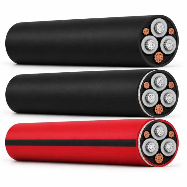
6-CHCU 3.6/6kV Mining Trailing and Reeling Cable
6-CHCU 3.6/6 kV trailing and reeling cable for excavators, stackers and stowing machines in open-pit mines, in base, TT and TTAR builds.
- Base 6-CHCU: single deflection direction, drum axis at right angle to travel.
- 6-CHCU-TT: polyester anti-torsion braid, multiple deflection directions.
- 6-CHCU TTAR: anti-torsion braid plus extra heavy-duty 5GM5 sheath.
- Conductor: fine stranded tinned copper, class 5.
- Range: 3 × 16 mm² to 3 × 185 mm².
Send machine type, drum geometry, deflection directions and pull for RFQ review.
6-CHCU 3.6/6 kV Mining Trailing and Reeling Cable
The 6-CHCU family covers three 3.6/6 kV screened cables for large open-pit machines, and the choice between them is decided by the winding geometry rather than by current. The base 6-CHCU build is for winding mechanisms with a single deflection direction, where the take-up drum axis sits at a right angle to the direction of travel. 6-CHCU-TT adds a polyester anti-torsion braid for mechanisms with various deflection directions, where the drum axis runs parallel to the machine. 6-CHCU TTAR keeps the anti-torsion braid and adds an extra heavy-duty 5GM5 sheath.
The three are not interchangeable on paper. The base build is rated to a +250 °C short-circuit temperature, while TT and TTAR are rated to +200 °C, and only TTAR carries published static and dynamic tensile load limits.
- Rated voltage: 3.6/6 kV; maximum operating voltage 7.2 kV for TT and TTAR.
- Cross-sections: 3 × 16 mm² to 3 × 185 mm².
- Route: base for single deflection, TT and TTAR for multiple deflection directions.
- Twist limit: ±50 °/m for TTAR.
For 20/35 kV machine feeding above this range see 35-CHVU trailing cable; for German-standard reel duty see R-(N)TSCGEWÖU reeling cable.
6-CHCU Family Construction and Selection
Select by winding geometry first, then by sheath duty. The table below is the decision the three builds exist to answer.
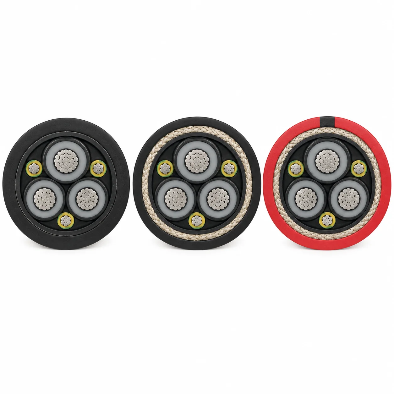
| Build | Winding geometry | Torsion protection | Outer sheath | Short-circuit temperature |
|---|---|---|---|---|
| 6-CHCU (base) | Single deflection direction; drum axis at right angle to travel direction | None | Chloroprene, black | +250 °C |
| 6-CHCU-TT | Various deflection directions; drum axis parallel to the equipment | Polyester braid | 5GM3 rubber, black | +200 °C |
| 6-CHCU TTAR | Severe trailing or reeling duty, multiple deflections | Polyester anti-torsion braid | 5GM5 rubber, red with black stripe | +200 °C |
Base 6-CHCU construction, to DS 073-2004
| No. | Layer |
|---|---|
| 1 | Fine stranded tinned copper conductor, class 5 |
| 2 | Semiconducting tape |
| 3 | Filler |
| 4 | Rubber insulation |
| 5 | Semiconducting layer |
| 6 | Semiconducting tape |
| 7 | Inner semiconducting sheath |
| 8 | Outer chloroprene sheath |
6-CHCU-TT construction, to DS 042-2005
| No. | Layer |
|---|---|
| 1 | Flexible stranded tinned copper conductor, class 5 |
| 2 | Inner semi-conducting layer of the working core |
| 3 | Core insulation, rubber compound type 3GI3 |
| 4 | Outer semi-conducting layer |
| 5 | Inner sheath |
| 6 | Torsion protection of polyester braiding |
| 7 | Outer sheath, rubber compound type 5GM3 |
6-CHCU TTAR construction
| No. | Layer |
|---|---|
| 1 | Tinned copper conductor, fine wire class 5 to DIN VDE 0295 |
| 2 | Inner conductive layer of main cores, semi-conductive tape |
| 3 | Insulation of main cores, EPR 3GI3 to DIN VDE 0207 Part 20, nominal wall 3.4 mm |
| 4 | Outer conductive layer of main cores, special conductive rubber compound, wall approx. 0.6 mm |
| 5 | Earth core, tinned copper fine stranded class 5 in conductive rubber compound |
| 6 | Cores laid up around a conductive filler with semi-conductive tape |
| 7 | Inner sheath, special conductive rubber compound |
| 8 | Sheath reinforcement, polyester anti-torsion braid |
| 9 | Outer sheath, rubber compound type 5GM5 to DIN VDE 0207 Part 21 |
6-CHCU Applications
The family supplies power to large mobile equipment in open-pit mines: coal extraction machines, excavators, stackers and stowing machines, on trailing and reeling routes under severe mechanical duty.
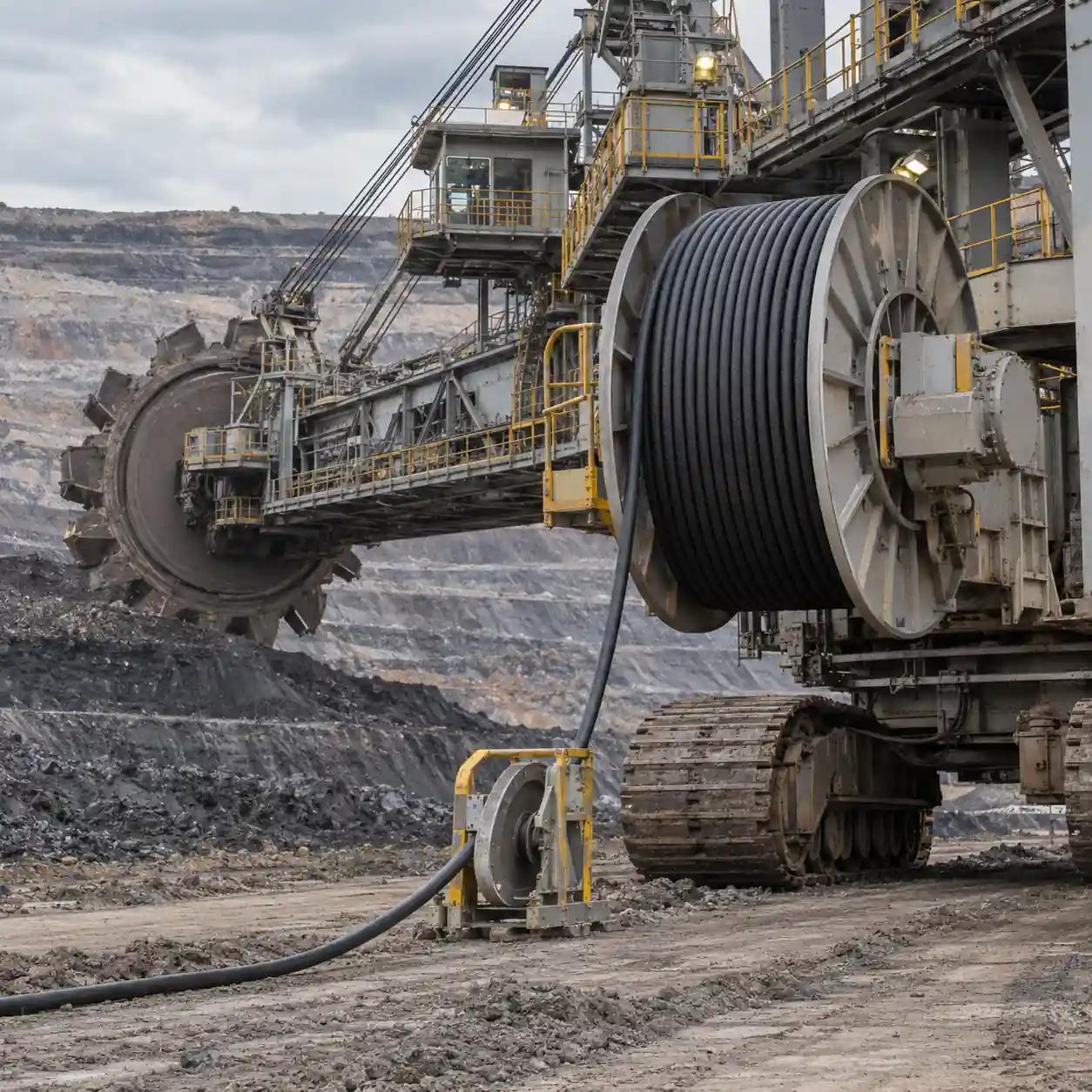
- Base 6-CHCU: coal extraction machines where the reel deflects the cable in one direction only.
- 6-CHCU-TT: excavators and stowing machines whose drum axis is parallel to the machine, producing multiple deflection directions.
- 6-CHCU TTAR: stackers and excavators on the most severe trailing or reeling duty, where sheath wear governs life.
- Surface routes exposed to shock, pressure, abrasion and weather.
Application boundaries
Use of flexible cables follows VDE 0298-3. Current ratings are free-in-air values at 30 °C and must be corrected twice: once for ambient temperature and again for the number of reeled layers, using the factors in the specifications tab. Reeling a cable in four layers removes well over half its rating. Drum diameter, deflection pulley diameter, number of layers, speed and pull determine which of the three builds applies.
Related mining reeling references
Compare 35-CHVU for 20/35 kV machine feeding, R-(N)TSCGEWÖU for German-standard reel duty and (N)TSCGEWÖU for semi-fixed mine distribution.
Reference note: enquiries arriving marked 6-CHCu, 6-CHCu-TT or 6-CHCu TTAR are handled on this page; spacing and capitalisation variants refer to the same family.
6-CHCU Specifications
| Property | 6-CHCU base | 6-CHCU-TT | 6-CHCU TTAR |
|---|---|---|---|
| Rated voltage U₀/U | 3.6/6 kV | 3.6/6 kV | 3.6/6 kV |
| Maximum operating voltage | - | 7.2 kV | 7.2 kV |
| Test voltage | 15 kV | 15 kV AC | 15 kV AC |
| Manufacturing standard | DS 073-2004 | DS 042-2005 | Letter code to ČSN 34 5127 |
| Max. short-circuit temperature | +250 °C | +200 °C | +200 °C |
| Conductor operating temperature | +90 °C | +90 °C | +90 °C |
| Surface temperature, fixed | -30 °C to +80 °C | -30 °C to +80 °C | -30 °C to +80 °C |
| Surface temperature, moved | -30 °C to +80 °C | -30 °C to +80 °C | -30 °C to +80 °C |
| Sheath colour | Black | Black | Red with black stripe |
Bending radius by build and route
| Condition | 6-CHCU base | 6-CHCU-TT | 6-CHCU TTAR |
|---|---|---|---|
| Fixed installation | See size table, in mm | 6 × D | 6 × D |
| Flexing / moving freely | See size table, in mm | 10 × D | 10 × D |
| On drums | - | - | 12 × D |
| On deflection pulleys | - | - | 15 × D |
| Twist limit | - | - | ±50 °/m |
TTAR bending radii follow DIN VDE 0298 Part 3, Table 2.
6-CHCU base and 6-CHCU-TT size and electrical table
The base and TT builds share one dimensional and electrical table.
| Code and cross-section | Outer diameter | Weight | Bending radius | Conductor resistance | Short-circuit current 1 s | Heating time constant | Current capacity in air | Capacitance | Inductance | Copper content |
|---|---|---|---|---|---|---|---|---|---|---|
| 6-CHCU 3 × 16 + 1 × 16 mm² | 43-49 mm | 2500 kg/km | 290 mm | 1.240 Ω/km | 1.95 kA | 156 s | 122 A | 0.24 µF/km | 0.389 mH/km | 627 kg/km |
| 6-CHCU 3 × 25 + 1 × 16 mm² | 46-51 mm | 2920 kg/km | 300 mm | 0.795 Ω/km | 3.05 kA | 290 s | 140 A | 0.27 µF/km | 0.361 mH/km | 892 kg/km |
| 6-CHCU 3 × 35 + 1 × 25 mm² | 49-54 mm | 3470 kg/km | 330 mm | 0.565 Ω/km | 4.27 kA | 290 s | 196 A | 0.29 µF/km | 0.345 mH/km | 1274 kg/km |
| 6-CHCU 3 × 50 + 3 × 16 mm² | 50-55 mm | 4050 kg/km | 340 mm | 0.393 Ω/km | 6.10 kA | 405 s | 237 A | 0.35 µF/km | 0.307 mH/km | 1940 kg/km |
| 6-CHCU 3 × 70 + 3 × 16 mm² | 54-59 mm | 4900 kg/km | 350 mm | 0.277 Ω/km | 8.54 kA | 526 s | 291 A | 0.38 µF/km | 0.293 mH/km | 2528 kg/km |
| 6-CHCU 3 × 95 + 3 × 16 mm² | 60-65 mm | 5950 kg/km | 380 mm | 0.210 Ω/km | 11.59 kA | 599 s | 370 A | 0.47 µF/km | 0.277 mH/km | 3263 kg/km |
| 6-CHCU 3 × 120 + 3 × 16 mm² | 63-68 mm | 7120 kg/km | 410 mm | 0.164 Ω/km | 14.64 kA | 783 s | 409 A | 0.49 µF/km | 0.272 mH/km | 3998 kg/km |
| 6-CHCU 3 × 150 + 3 × 25 mm² | 67-73 mm | 8620 kg/km | 450 mm | 0.132 Ω/km | 18.30 kA | 967 s | 460 A | 0.51 µF/km | 0.261 mH/km | 5145 kg/km |
| 6-CHCU 3 × 185 + 3 × 35 mm² | 71-77 mm | 9650 kg/km | 480 mm | 0.108 Ω/km | 22.57 kA | 1108 s | 530 A | 0.58 µF/km | 0.256 mH/km | 6468 kg/km |
6-CHCU TTAR size, weight and tensile load table
| Code and cross-section | Main conductor diameter | Outside diameter | Weight | Max. static tensile load | Max. dynamic tensile load |
|---|---|---|---|---|---|
| 6-CHCU TTAR 3 × 16 + 16 mm² | 5.6 mm | 43-49 mm | 2910 kg/km | 960 N | 1600 N |
| 6-CHCU TTAR 3 × 25 + 16 mm² | 6.6 mm | 46-51 mm | 3390 kg/km | 1365 N | 2275 N |
| 6-CHCU TTAR 3 × 35 + 25 mm² | 7.7 mm | 49-54 mm | 3920 kg/km | 1575 N | 2625 N |
| 6-CHCU TTAR 3 × 50 + 3 × 16 mm² | 9.3 mm | 52-57 mm | 4660 kg/km | 2250 N | 3750 N |
| 6-CHCU TTAR 3 × 70 + 3 × 16 mm² | 11.5 mm | 55-60 mm | 5710 kg/km | 3150 N | 5250 N |
| 6-CHCU TTAR 3 × 95 + 3 × 16 mm² | 13.2 mm | 60-65 mm | 6950 kg/km | 4275 N | 7125 N |
| 6-CHCU TTAR 3 × 120 + 3 × 16 mm² | 14.9 mm | 63-68 mm | 8170 kg/km | 5400 N | 9000 N |
| 6-CHCU TTAR 3 × 150 + 3 × 25 mm² | 16.5 mm | 67-73 mm | 9195 kg/km | 6750 N | 11250 N |
| 6-CHCU TTAR 3 × 185 + 3 × 35 mm² | 18.4 mm | 71-77 mm | 11150 kg/km | 8325 N | 13875 N |
6-CHCU TTAR electrical table
| Code and cross-section | Main core resistance at 20 °C | Inductive resistance at 50 Hz | Core-to-earth capacitance | Current rating, straight laid at 30 °C | Short-circuit current 90-200 °C, 1 s |
|---|---|---|---|---|---|
| 6-CHCU TTAR 3 × 16 + 16 mm² | 1.240 Ω/km | 0.122 Ω/km | 0.27 µF/km | 99 A | 1.95 kA |
| 6-CHCU TTAR 3 × 25 + 16 mm² | 0.795 Ω/km | 0.112 Ω/km | 0.34 µF/km | 131 A | 3.05 kA |
| 6-CHCU TTAR 3 × 35 + 25 mm² | 0.565 Ω/km | 0.107 Ω/km | 0.38 µF/km | 162 A | 4.27 kA |
| 6-CHCU TTAR 3 × 50 + 3 × 16 mm² | 0.393 Ω/km | 0.101 Ω/km | 0.42 µF/km | 202 A | 6.10 kA |
| 6-CHCU TTAR 3 × 70 + 3 × 16 mm² | 0.277 Ω/km | 0.090 Ω/km | 0.48 µF/km | 250 A | 8.54 kA |
| 6-CHCU TTAR 3 × 95 + 3 × 16 mm² | 0.210 Ω/km | 0.092 Ω/km | 0.53 µF/km | 301 A | 11.59 kA |
| 6-CHCU TTAR 3 × 120 + 3 × 16 mm² | 0.164 Ω/km | 0.089 Ω/km | 0.59 µF/km | 352 A | 14.64 kA |
| 6-CHCU TTAR 3 × 150 + 3 × 25 mm² | 0.132 Ω/km | 0.087 Ω/km | 0.63 µF/km | 404 A | 18.30 kA |
| 6-CHCU TTAR 3 × 185 + 3 × 35 mm² | 0.108 Ω/km | 0.085 Ω/km | 0.69 µF/km | 461 A | 22.57 kA |
The short-circuit constant k = 122 is calculated to IEC 60949 for a 200 °C short-circuit temperature and a 90 °C conductor temperature.
Current rating correction factors
| Ambient temperature | 20 °C | 35 °C | 40 °C | 45 °C | 50 °C |
|---|---|---|---|---|---|
| Factor | 1.1 | 0.95 | 0.89 | 0.84 | 0.77 |
| Reeled in layers | Spiral | 1 | 2 | 3 | 4 |
|---|---|---|---|---|---|
| Factor | 0.8 | 0.8 | 0.61 | 0.49 | 0.42 |
All cross-sections in all three builds are available to order.
6-CHCU Standards, Approvals and Order Documentation
| Reference | Scope | Applies to |
|---|---|---|
| DS 073-2004 | Manufacturing specification | 6-CHCU base |
| DS 042-2005 | Manufacturing specification | 6-CHCU-TT |
| ČSN 34 5127 | Letter code designation | 6-CHCU TTAR |
| DIN VDE 0295 | Class 5 conductor stranding | All builds |
| DIN VDE 0207 Parts 20 and 21 | 3GI3 insulation and 5GM3/5GM5 sheathing compounds | TT and TTAR |
| DIN VDE 0298-3 | Guide to use for flexible cables, and bending radii Table 2 | All builds |
| DIN VDE 0298-4 | Current rating correction, Tables 17 and 27 | All builds |
| IEC 60949 | Short-circuit current calculation, k = 122 | TTAR |
Approvals
| Approval | Status |
|---|---|
| Manufacturing conformity, DS 073-2004 and DS 042-2005 | Held |
| Medium-voltage routine electrical test package, 15 kV AC | Held |
| Partial discharge test | Held |
Order package
State which build is required, the machine and its rating, drum diameter and axis orientation, deflection pulley diameter, number of reeled layers, travel speed, expected pull against the TTAR tensile limits, ambient temperature, required drum lengths, marking string and any project inspection or documentation scope.
Related cable options
Compare these cable options by service combination, movement, load, voltage and transmission requirement.
R-(N)TSCGEWÖU Medium Voltage Reeling Cable 3.6/6–18/30 kV
For continuous drum reeling and higher dynamic movement.
View product
(N)TSCGEWÖU Cable 3.6/6kV to 12/20kV Mine Distribution Cable
A related cable option for a different application or duty profile.
View product
35-CHVU 20/35kV Open-Pit Mining Trailing Cable
A related cable option for a different application or duty profile.
View productRequest a cable recommendation and quotation
Send the required services, cable length, mechanical duty, environment, termination and quantity. Our team will review the application before quoting.
- Include the product name or SKU plus the required cable length and quantity.
- Attach a specification, drawing or data sheet when available.