

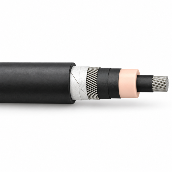
(N)TMCGCHXOEUK 26/45 kV Cold-Resistant Pantograph and Jumper Cable
Cold-resistant, single-core 26/45 kV railway cable with separate pantograph and coach-jumper screen constructions, HEPR insulation and black cross-linked polyolefin sheath.
(N)TMCGCHXOEUK is a 26/45 kV single-core railway cable design for pantograph and overhead-line connections in cold rolling-stock environments. The supplied reference has finely stranded Class 5 tinned copper, semiconductive field-control layers, cross-linked HEPR-based insulation and a black halogen-free cross-linked polyolefin sheath. Its reference temperature window reaches −55°C for fixed installation and fully flexible operation; the conductor maximum is 90°C.
Two applications sit under this model designation. The ordinary pantograph construction has a stranded layer of tinned-copper screen wires and serves short electrical links to switchgear or mobile transformer equipment. The coach-jumper version uses a tinned-copper braided screen for flexible inter-car power connections. They share voltage and many dimensions, but their metallic screen constructions and the intended movement pattern differ. Specify pantograph or jumper on the order rather than choosing only by cross-section.
The supplied tables list 13 1-core/metallic-screen area combinations for each version, from 1 × 50/16 through 1 × 630/35 mm². They include conductor and finished diameters, cable mass, free-air current and a 1-second short-circuit current reference. Route length, bending, termination, movement, grounding and local rolling-stock fire requirements must be checked for the selected assembly; do not use an unverified generic rail-cable value for a jumper.
Compare the existing (N)TMCWOEU 26/45 kV railway cable and browse industrial cable constructions when choosing between rail supply designs.
Lower-voltage interconnecting wiring on locomotives, trolleybuses and other track-bound vehicles is a separate selection: the CGAU single-core vehicle cable covers the 2/3.6 and 3.6/6 kV ratings from 2.5 to 16 mm², with rubber insulation and a black CPE sheath.
Both reference versions have a tinned, fine-stranded Class 5 copper conductor, inner and outer semiconductive rubber field-control layers, HEPR-based cross-linked insulation and a black cross-linked halogen-free polyolefin sheath. The normal pantograph version uses a stranded layer of tinned-copper wires between separating layers. The jumper version uses a braid of tinned-copper wires between separating layers; that difference is central to the inter-car movement duty.
The source describes a cold-strippable core screen. Confirm termination and screen-bonding details against the approved drawing for each version; the separate wire-screen and braid-screen views below identify the two constructions.
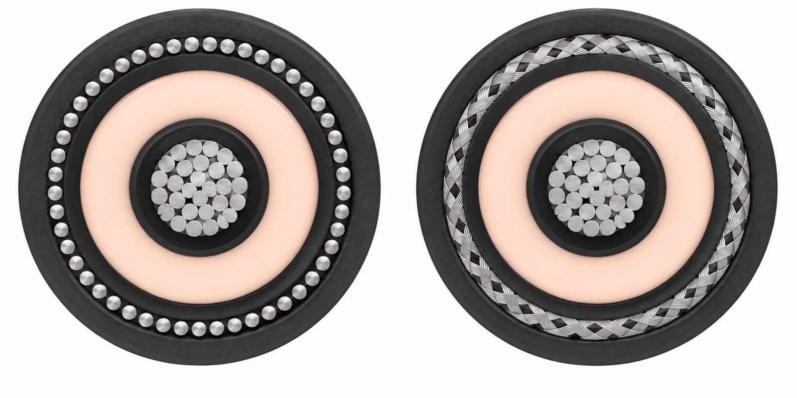
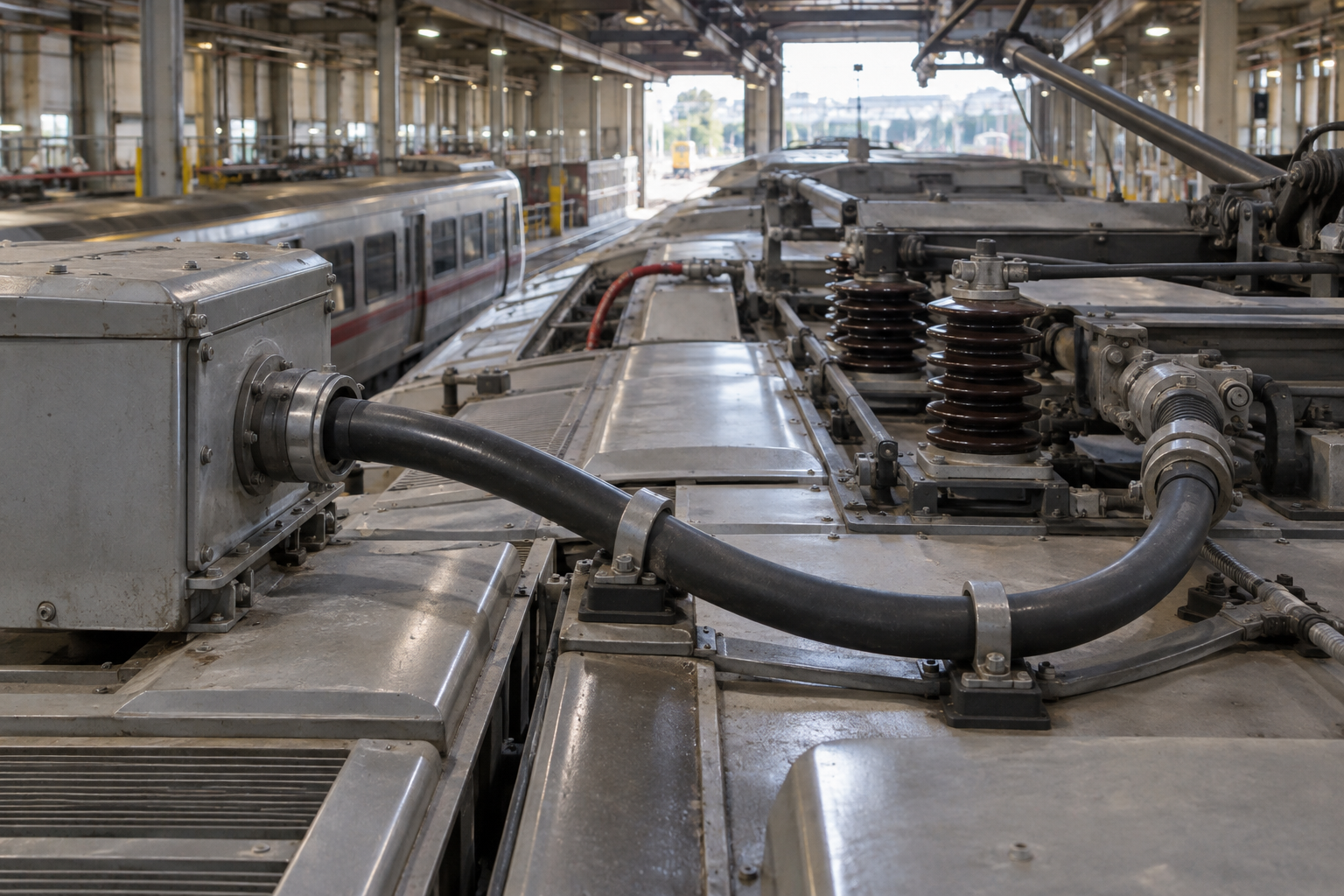
Use the pantograph build for short locomotive or train connections involving the pantograph, switchgear cubicle or transformer supply. Use the separately specified jumper build for a coach-to-coach power connection where movement during operation is expected. The source allows rail-vehicle indoor and outdoor routing but calls for protection against excessive mechanical stress.
Selection should include the intended movement, fixed and service bend geometry, clamp positions, terminal interfaces, screen/earth connection, installation temperature and any rail fire requirements. The 26/45 kV designation is a high-voltage rail power circuit; termination and clearances must be engineered for the installation rather than inferred from a cable size alone.
Both structures have the same nominal 26/45 kV designation. The supplied source lists maximum permissible AC operating voltage 31/54 kV, DC 40.5/81 kV, 65 kV AC test for five minutes, 250 kV impulse reference and maximum partial discharge of 5 pC at 52 kV. Conductor reference is 90°C continuous and 250°C short circuit, up to five seconds.
| Model + configuration | Conductor OD (mm) | OD over screen (mm) | Outer OD min (mm) | Outer OD max (mm) | Approx. weight (kg/km) | Current in free air (A)* | 1 s conductor short-circuit (kA) |
|---|---|---|---|---|---|---|---|
| (N)TMCGCHXOEUK 26/45 kV 1×50/16 mm² pantograph | 9 | 30.4 | 36 | 38 | 1900 | 309 | 7.15 |
| (N)TMCGCHXOEUK 26/45 kV 1×70/16 mm² pantograph | 10.8 | 32.2 | 38 | 40 | 2400 | 379 | 10 |
| (N)TMCGCHXOEUK 26/45 kV 1×95/16 mm² pantograph | 12.6 | 34 | 40.5 | 42.5 | 2700 | 457 | 13.6 |
| (N)TMCGCHXOEUK 26/45 kV 1×95/25 mm² pantograph | 12.6 | 34.2 | 40.7 | 42.7 | 2700 | 457 | 13.6 |
| (N)TMCGCHXOEUK 26/45 kV 1×120/16 mm² pantograph | 14.2 | 35.6 | 43 | 45 | 3000 | 531 | 17.2 |
| (N)TMCGCHXOEUK 26/45 kV 1×120/25 mm² pantograph | 14.2 | 35.8 | 43.2 | 45.2 | 3000 | 531 | 17.2 |
| (N)TMCGCHXOEUK 26/45 kV 1×150/25 mm² pantograph | 15.8 | 37.4 | 44.5 | 46.5 | 3700 | 613 | 21.5 |
| (N)TMCGCHXOEUK 26/45 kV 1×185/25 mm² pantograph | 17.4 | 39 | 46.5 | 48.5 | 4200 | 699 | 26.6 |
| (N)TMCGCHXOEUK 26/45 kV 1×240/25 mm² pantograph | 20.4 | 42 | 49 | 51 | 4500 | 823 | 34.3 |
| (N)TMCGCHXOEUK 26/45 kV 1×300/35 mm² pantograph | 22.9 | 44.7 | 52 | 54 | 5400 | 945 | 42.9 |
| (N)TMCGCHXOEUK 26/45 kV 1×400/35 mm² pantograph | 26.2 | 48 | 55 | 57 | 6400 | 1145 | 57.2 |
| (N)TMCGCHXOEUK 26/45 kV 1×500/35 mm² pantograph | 29.5 | 51 | 59 | 62 | 7400 | 1288 | 71.5 |
| (N)TMCGCHXOEUK 26/45 kV 1×630/35 mm² pantograph | 33.6 | 55.1 | 64 | 68 | 9200 | 1432 | 90.1 |
| Model + configuration | Conductor OD (mm) | OD over screen (mm) | Outer OD min (mm) | Outer OD max (mm) | Approx. weight (kg/km) | Current in free air (A)* | 1 s conductor short-circuit (kA) |
|---|---|---|---|---|---|---|---|
| (N)TMCGCHXOEUK 26/45 kV 1×50/16 mm² jumper | 9 | 30.4 | 36 | 38 | 1900 | 309 | 7.15 |
| (N)TMCGCHXOEUK 26/45 kV 1×70/16 mm² jumper | 10.8 | 32.2 | 38 | 40 | 2400 | 379 | 10 |
| (N)TMCGCHXOEUK 26/45 kV 1×95/16 mm² jumper | 12.6 | 34 | 40.5 | 42.5 | 2700 | 457 | 13.6 |
| (N)TMCGCHXOEUK 26/45 kV 1×95/25 mm² jumper | 12.6 | 34.2 | 40.7 | 42.7 | 2700 | 457 | 13.6 |
| (N)TMCGCHXOEUK 26/45 kV 1×120/16 mm² jumper | 14.2 | 35.6 | 43 | 45 | 3000 | 531 | 17.2 |
| (N)TMCGCHXOEUK 26/45 kV 1×120/25 mm² jumper | 14.2 | 35.8 | 43.2 | 45.2 | 3000 | 531 | 17.2 |
| (N)TMCGCHXOEUK 26/45 kV 1×150/25 mm² jumper | 15.8 | 37.4 | 44.5 | 46.5 | 3700 | 613 | 21.5 |
| (N)TMCGCHXOEUK 26/45 kV 1×185/25 mm² jumper | 17.4 | 39 | 46.5 | 48.5 | 4200 | 699 | 26.6 |
| (N)TMCGCHXOEUK 26/45 kV 1×240/25 mm² jumper | 20.4 | 42 | 49 | 51 | 4500 | 823 | 34.3 |
| (N)TMCGCHXOEUK 26/45 kV 1×300/35 mm² jumper | 22.9 | 44.7 | 52 | 54 | 5400 | 945 | 42.9 |
| (N)TMCGCHXOEUK 26/45 kV 1×400/35 mm² jumper | 26.2 | 48 | 55 | 57 | 6400 | 1145 | 57.2 |
| (N)TMCGCHXOEUK 26/45 kV 1×500/35 mm² jumper | 29.5 | 51 | 59 | 62 | 7400 | 1288 | 71.5 |
| (N)TMCGCHXOEUK 26/45 kV 1×630/35 mm² jumper | 33.6 | 55.1 | 64 | 68 | 9200 | 1432 | 90.1 |
*The source free-air current data are for one cable at 90°C conductor and 30°C ambient, AC 50–60 Hz or DC. Mass is approximate. The table's 1-second short-circuit figures refer to conductor size, not a blanket rating of each termination or complete assembly. Review the specific screen type and final dimensional tolerance before procurement.
The source describes the cable designs as based on DIN VDE 0250-813 and IEC 60840:2011 and references IEC 60228 Class 5 for conductor stranding. It also names DIN EN 50343 for installation of rolling-stock cabling and DIN EN 50124-2 / DIN EN 50163 for railway overvoltage conditions. State the edition and required test evidence in the project specification for the ordered construction.
Related cable options
Compare these cable options by service combination, movement, load, voltage and transmission requirement.
26/45 kV (N)TMCWOEU Railway Cable
A related cable option for a different application or duty profile.
View product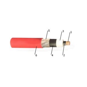
NTMCWOEU 26/45 kV Flexible Switchgear Cable
A related cable option for a different application or duty profile.
View productRequest a cable recommendation and quotation
Send the required services, cable length, mechanical duty, environment, termination and quantity. Our team will review the application before quoting.
- Include the product name or SKU plus the required cable length and quantity.
- Attach a specification, drawing or data sheet when available.