

Project record · Russian buyer · Civil airport · Pit system for 400 Hz aircraft ground power
400 Hz Ground Power Cable for an Airport Pit System: 450 m of 4×(1×70+4×1) PUR Cable for a Russian Buyer
A Russian end user that assembles aviation power equipment itself ordered 450 m of 400 Hz ground power cable to connect a pit system at a civil airport to parked aircraft. TEBAOFLEX made it as four separately sheathed cores twisted together, printed 4×(1×70+4×1). Each core is one 70 mm² tinned copper power conductor and four 1 mm² FEP-insulated control cores in black EPR insulation, under its own yellow polyurethane (PUR) sheath. The buyer makes the cable up into 15 m and 28 m assemblies and fits the aircraft connectors itself, which were ordered from TEBAOFLEX together with the cable. The drums were lagged and loaded into a shipping container on 28 September 2026.
Project at a glance
| Application | Pit system on the apron of a civil airport: the cable connects the pit equipment to the 400 Hz ground power receptacle of parked aircraft |
|---|---|
| Customer | Russian end user that assembles aviation power equipment itself (name not published) |
| Cable | TEBAOFLEX Aircraft 400 Hz Ground Power Supply Cable 4×(1×70+4×1): four cores, each one 70 mm² power conductor and four 1 mm² control cores under a yellow PUR sheath |
| Quantity | 450 m |
| Assemblies | 15 m and 28 m lengths, cut and assembled by the buyer |
| Connectors | 400 Hz aircraft connectors ordered from TEBAOFLEX together with the cable; fitted by the buyer |
| Temperature range offered | Flexible service −40 °C to +90 °C; fixed installation −50 °C to +90 °C |
| Production record | Conductor stranding filmed on 21 September 2026; four-core lay-up on 24 September; drums wrapped on 26 September |
| Status | Drums lagged and loaded into a shipping container on 28 September 2026 |
What is an aircraft ground power pit system?
An aircraft ground power pit system brings 400 Hz power, and on some stands preconditioned air and water, to the aircraft stand through pits below the apron. The ground power cable is stored in the pit when the stand is not in use, loose or on a retractor, and brought out to the parked aircraft when needed. The stand is served without a mobile ground power unit, and the apron stays clear. In this project the cable runs from the equipment in the pit to the aircraft's 400 Hz receptacle.
- 400 Hz supply for the stand, for example a frequency converter in a central plant or at the stand
- Feeder cable under the apron to the pit (not part of this order)
- Pit below the apron surface, closed with a hatch when the stand is not in use
- Connection and control equipment inside the pit, where the ground power cable is connected
- The 400 Hz ground power cable of this order, pulled out of the pit and laid across the apron; the buyer makes it up in 15 m and 28 m assemblies
- 400 Hz aircraft connector on the cable end, fitted by the buyer
- Ground power receptacle of the parked aircraft
- Apron surface
The supply follows ISO 6858:2017, the international standard for aircraft ground support electrical supplies. It covers three-phase 400 Hz at 115/200 V or 230/400 V, plus 28 V DC, and defines the electrical characteristics at the connector where the cable attaches to the aircraft. That reference point is what makes the cable part of the power system rather than an accessory: whatever the cable loses between the pit and the aircraft is lost from the supply the aircraft sees. Other airport duties, from mobile ground power units to boarding bridges and cable reels, are compared in our airport ground power cable solutions.
What does 4×(1×70+4×1) mean on a ground power cable?
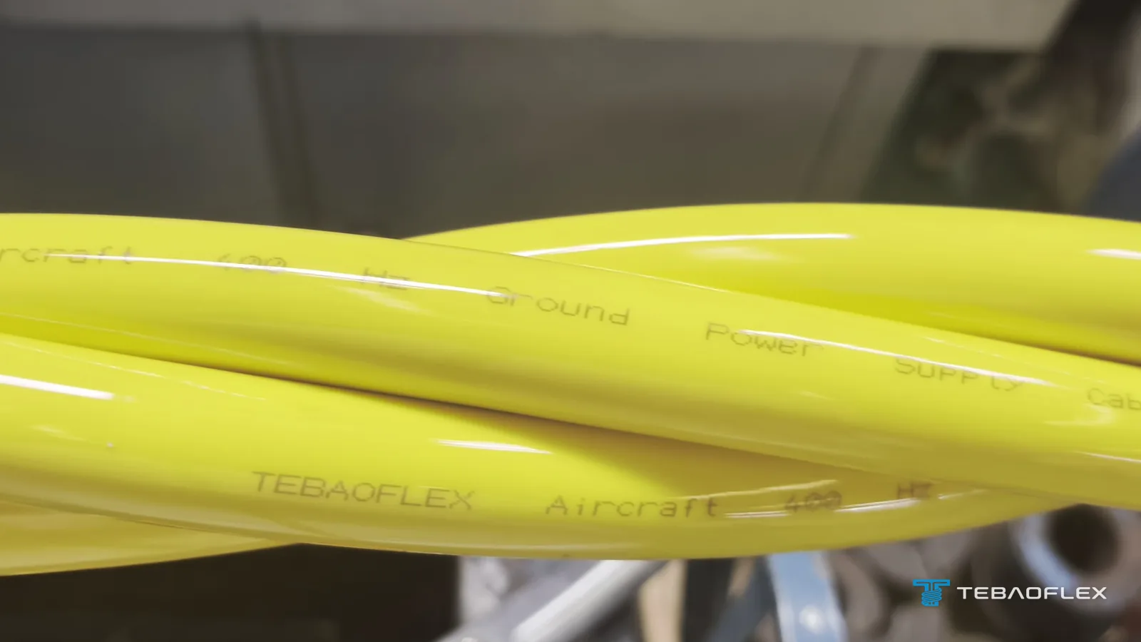
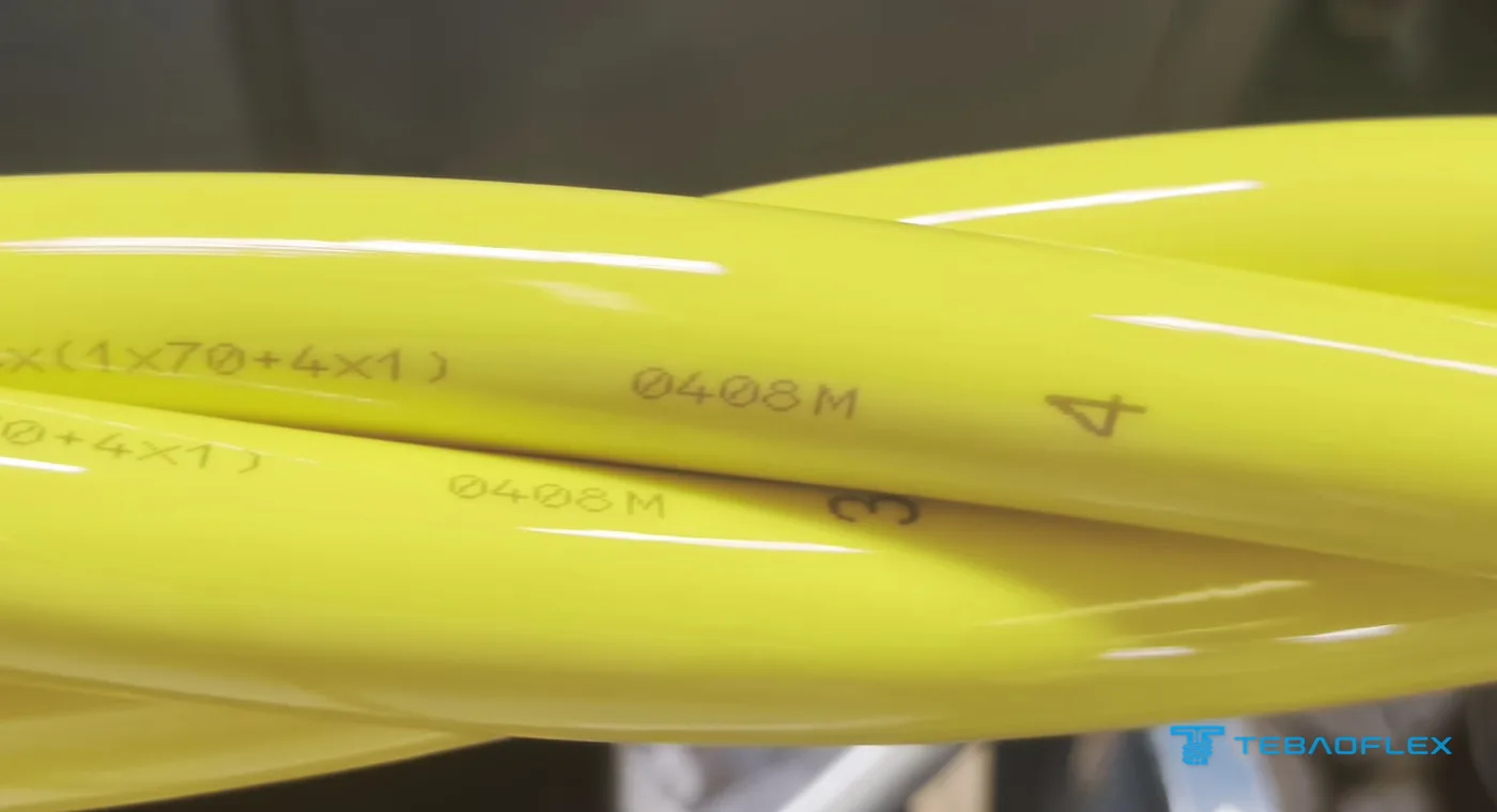
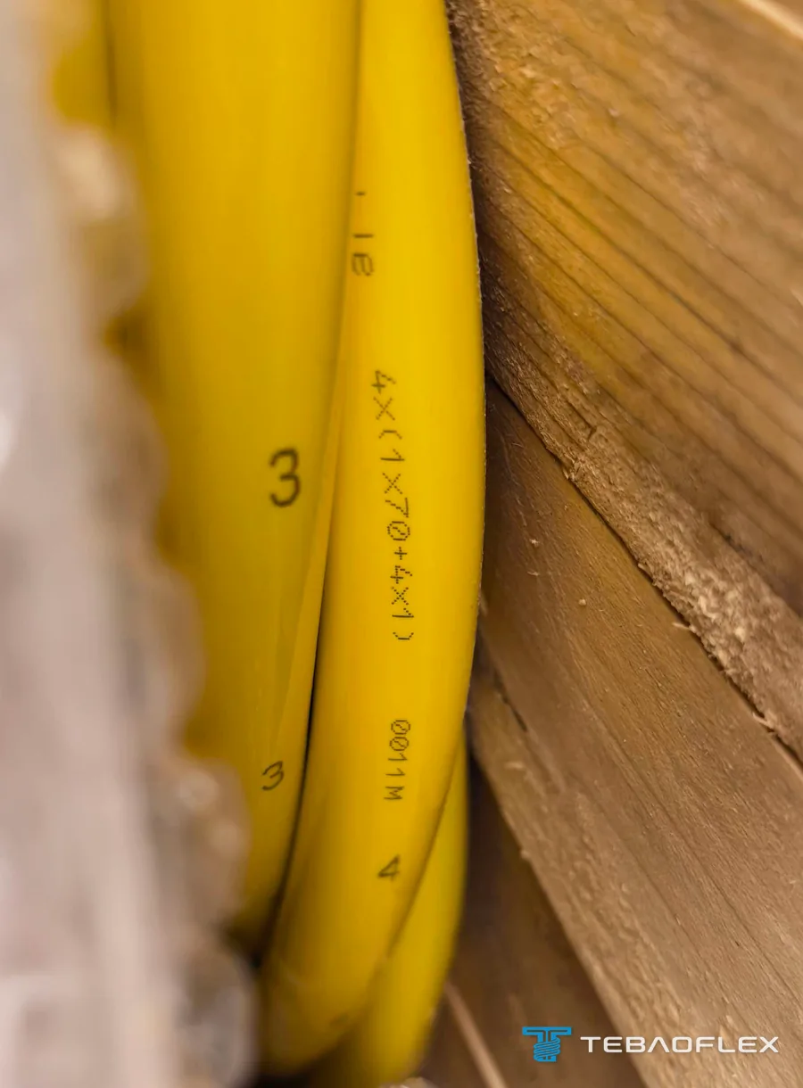
4×(1×70+4×1) describes four identical cores. Each core, 1×70+4×1, is one 70 mm² power conductor plus four 1 mm² control cores under its own sheath. Twisted together, the four cores give four 70 mm² power conductors for the three phases and the neutral of the 400 Hz supply, and sixteen 1 mm² control cores. On this order every core sheath is printed with the full designation, a metre marking and its core number, 1 to 4.
- Power conductor: 70 mm², fine tinned copper wires, IEC 60228 Class 5
- Insulation: cross-linked EPR (ethylene propylene rubber), black, around the power conductor and the control cores
- Control cores: 4 × 1 mm² per core, fine tinned copper wires, IEC 60228 Class 6, laid along the power conductor, two on each side, inside the EPR layer
- Control-core insulation: FEP, grey, each core numbered in white
- Core sheath: abrasion-resistant polyurethane (PUR), yellow, printed with the designation, the metre marking and the core number
- Four cores twisted together, numbered 1 to 4; there is no overall sheath
| Item | This order |
|---|---|
| Sheath print | TEBAOFLEX Aircraft 400 Hz Ground Power Supply Cable 4×(1×70+4×1), metre marking, core number |
| Power conductors | 4 × 70 mm², fine tinned copper wires, IEC 60228 Class 5 |
| Insulation | Cross-linked EPR, black, around the power conductor and its four control cores |
| Control cores | 4 × 1 mm² in each core, 16 in total; fine tinned copper wires, IEC 60228 Class 6 (VDE 0295) |
| Control-core insulation | FEP, grey, numbered in white |
| Core sheath | Abrasion-resistant PUR, yellow, one sheath per core; no overall sheath |
| Core identification | Numbers 1 to 4 printed along each core |
| Temperature range offered | Flexible service −40 °C to +90 °C; fixed installation −50 °C to +90 °C |
The power conductors are insulated with EPR, a rubber insulation widely used in flexible power cables because it stays flexible and keeps its electrical properties in wet service. Why flexible cables use EPR rather than XLPE is explained in our EPR insulation guide. The control cores are insulated with FEP, a fluoropolymer that allows a thin insulation wall, which keeps four 1 mm² cores small enough to sit along the 70 mm² conductor, two on each side, inside its EPR layer.
Why four separately sheathed cores twisted together?
Four individually sheathed cores twisted together, with no common sheath over them, give a flexible 400 Hz ground power cable that can be pulled out of a pit, laid across the apron and plugged into an aircraft. Each core of this order carries its own abrasion-resistant PUR sheath, so there is no overall jacket to strip at the connector, and each core can be identified by its printed number and terminated on its own.
The twist also does electrical work. At 400 Hz the inductive reactance of a cable is about eight times its value at 50 Hz, because reactance rises in proportion to frequency (X = 2πfL). Inductance grows with the distance between the conductors that carry the current out and back. Keeping the four cores tight together along the whole length keeps the phase conductors close and the inductance low, and the twist holds that spacing fixed along the length and keeps the stray magnetic field low. All four cores are the same yellow, so the printed numbers are what tells the installer which core is which phase, and which is the neutral, at both ends of every assembly.
Why the cut length matters at 400 Hz: the 15 m and 28 m assemblies
At 400 Hz the inductive reactance of a ground power cable is about eight times its 50 Hz value, and for a 70 mm² conductor it outweighs the resistance. The length of each assembly, with the load and its power factor, therefore sets how much voltage is lost between the pit and the aircraft. During the enquiry TEBAOFLEX asked the buyer how long each cut piece would be, because its engineers were evaluating the impedance of the cable; the answer was 15 m and 28 m.
Because ISO 6858 defines the supply at the aircraft connector, the ground power equipment has to deliver the cable's voltage drop on top of what the aircraft needs. A longer assembly, a higher load or an unbalanced load between the phases all increase the drop. For a new pit system cable, send the length of every assembly with the aircraft load and the voltage the ground power equipment can deliver at the pit. The conductor size can then be checked against the actual length rather than a catalogue value.
What do the control cores in a 400 Hz ground power cable carry?
The control cores in a 400 Hz ground power cable carry low-voltage signals between the aircraft connector and the ground power equipment, in the same cable as the power conductors. The best-known is the interlock, which lets the 400 Hz supply switch on only while the connector is fully engaged in the aircraft receptacle and switches it off when the connector is withdrawn. This order has sixteen 1 mm² control cores, four in each power core, numbered for identification; which of them the buyer uses for the interlock, for monitoring or as spares is set by its own connector wiring.
Keeping the control cores inside each power core, rather than in a separate control cable, means they are pulled out, laid and stowed together with the power conductors, and protected by the same PUR sheath. The dimensions of the 400 Hz connectors that terminate them are standardised in ISO 461-2, which covers the three-phase 400 Hz connector styles on the aircraft and on the ground supply side.
Will a PUR sheath crack at −40 °C on the apron?
Whether a PUR sheath cracks when a ground power cable is repeatedly reeled and dragged at −40 °C depends on the PUR grade, because polyurethanes differ widely in low-temperature flexibility. The buyer of this order asked exactly that about a cable offered for flexible service from −40 °C to +90 °C. TEBAOFLEX answered that the PUR grade is selected for the buyer's actual service conditions.
The way to verify a grade is to test the sheath at the temperature the project specifies. For cores of this size the usual low-temperature tests are an elongation test, IEC 60811-505, and an impact test, IEC 60811-506; the bending test of IEC 60811-504 suits smaller diameters. Product standards normally call them up as type tests on samples, not checks on each drum, so a buyer who needs them should write them into the enquiry and the test plan as sample tests, with the test temperature. The other properties a pit cable needs from its sheath, resistance to abrasion against concrete and to the fuels, oils and de-icing fluids on an apron, belong in the same specification.
How the cable was made: from stranded conductor to four-core lay-up
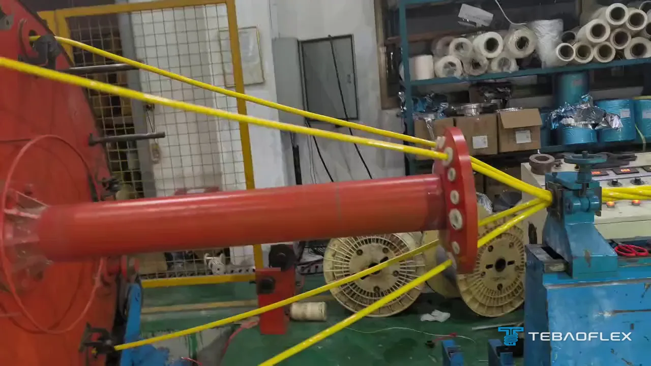
The cable was made in the TEBAOFLEX factory in September 2026. The 70 mm² conductors were stranded from fine tinned copper wires, filmed on 21 September. Each conductor was insulated with EPR together with its four control cores and sheathed in yellow PUR, giving four single cores numbered 1 to 4, each wound on its own reel. On 24 September the four cores were twisted together on a lay-up machine and wound onto the shipping drums.

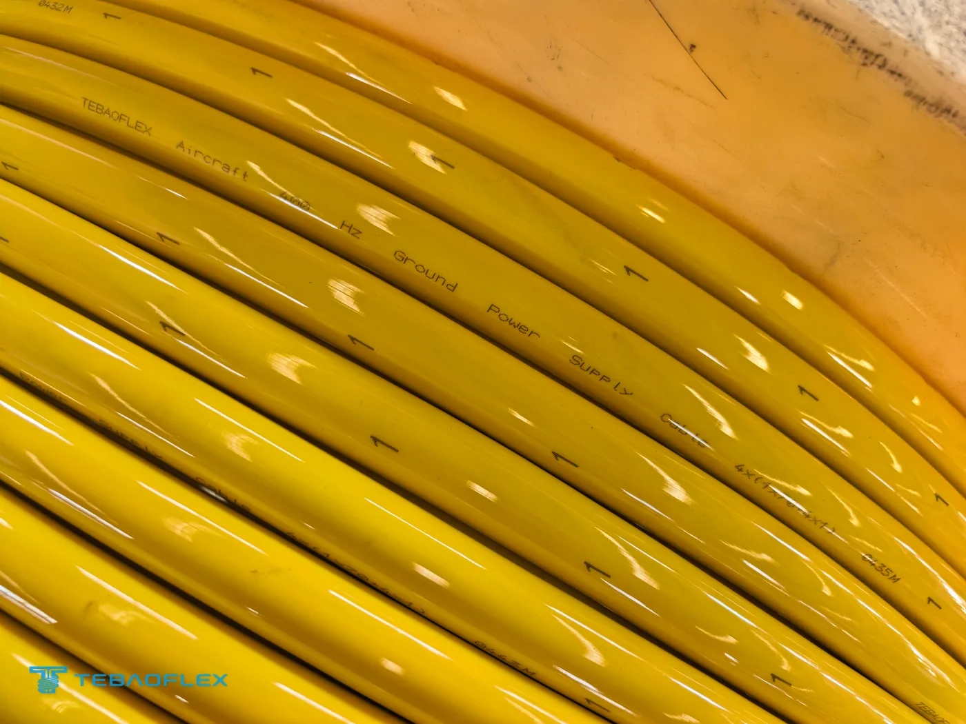

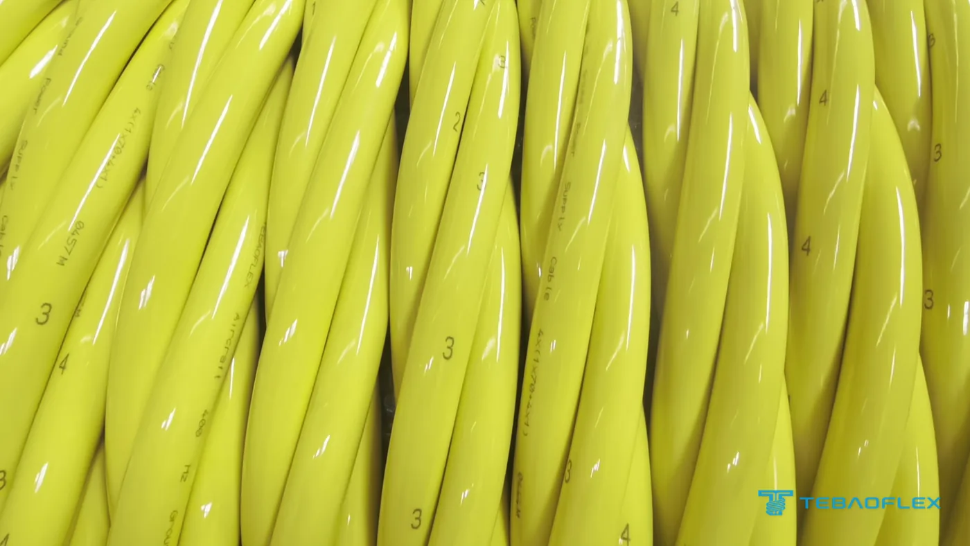
The metre marking on each core and the core numbers make the cable traceable along its length: the installer can read how much is left on a drum, and each cut piece carries its own core identification at both ends.
Connectors: ordered with the cable, fitted by the buyer
The buyer needed 400 Hz aircraft connectors as well as the cable and fits them itself, because it has its own assembly capability; the connectors were therefore ordered from TEBAOFLEX together with the cable, rather than finished assemblies. For this order TEBAOFLEX quoted about 20 days to produce the cable and 35 to 40 days for the connectors, and the buyer chose to receive cable and connectors in one shipment rather than the cable first.
When a buyer fits its own connectors, the enquiry should name the connector it will use, because the connector decides how the cable is prepared. It sets the core diameter the cable entry or strain relief must accept, the contact sizes for the 70 mm² conductors and the 1 mm² control cores, and how much of each core sheath is removed at the termination. Where a ready-made cable assembly is wanted instead, say so; the 400 Hz products and assemblies we make are listed in our airport ground power cable range.
Packing and shipment
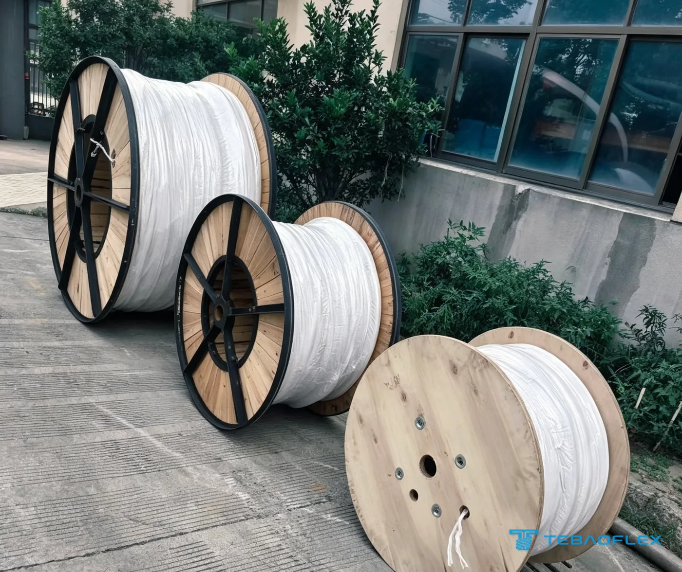
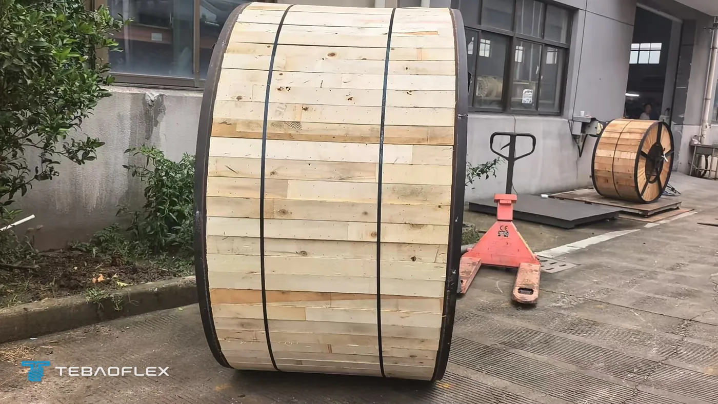
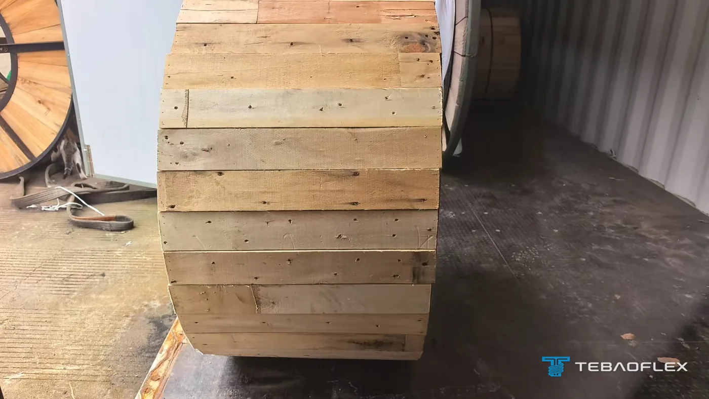
The drums of this order were wrapped in protective film on 26 September 2026, closed with wooden lagging boards and steel straps, and loaded into a shipping container on 28 September 2026. Lagging the drums keeps forks, lashing and other cargo away from the yellow PUR sheaths in transit.
What to send for a 400 Hz ground power cable quote
- Where the cable is used: pit system, cable reel or retriever, passenger boarding bridge or mobile ground power unit
- Supply: 115/200 V or 230/400 V, 400 Hz, and the load of the aircraft served
- Length of every assembly and the number of assemblies of each length
- Conductor arrangement: power conductors and control cores, and what the control cores are used for
- Connector type, and whether you fit the connectors yourself or need finished assemblies
- Lowest handling temperature, and any cold-bend or cold-impact test you require
- Apron conditions: abrasion, fuels, oils, de-icing fluids, sunlight
- Sheath colour and marking, if your airport has a standard
- Documents required with the delivery, and the delivery country
Our catalogue four-core 400 Hz cable, with a different control-core arrangement, is on our 400 Hz aircraft ground power cable page. Cables for motorised reels are on the 400 Hz cable for GPU cable reels page, and 28 V DC ground power cables on the 28 V DC ground power cable page. As of August 2026, TEBAOFLEX's minimum order is 50 m for standard and custom cables alike. Lead times range from 7 to 45 working days depending on the product type and its customisation; the written quotation confirms the lead time for your order, and transit and customs time depend on the route.
Send your assembly lengths and connector type for a quote →
Questions on 400 Hz ground power cable for pit systems
What size cable does an aircraft ground power pit system need?
There is no single size: the conductor size of a pit system cable follows the aircraft load, the length of each assembly and the voltage the aircraft must receive at its connector. In this order from a Russian buyer for a civil airport, the buyer specified four 70 mm² power conductors, each with four 1 mm² control cores (4×(1×70+4×1)), made up in 15 m and 28 m assemblies.
Why does cable length matter more at 400 Hz than at 50 Hz?
Cable length matters more at 400 Hz because inductive reactance rises in proportion to frequency (X = 2πfL). The same cable has about eight times the reactance at 400 Hz that it has at 50 Hz, so each metre drops more voltage, and the drop over an assembly grows with its length. ISO 6858 defines the 400 Hz supply at the aircraft connector, so every metre of cable counts against it.
Can a PUR-sheathed ground power cable be reeled and dragged at −40 °C?
A PUR-sheathed ground power cable can be reeled and dragged at −40 °C only if its PUR grade stays flexible at that temperature; polyurethanes differ widely in cold performance. The 4×(1×70+4×1) cable of this order was offered for flexible service from −40 °C to +90 °C. To verify a grade on cores of this size, specify a low-temperature elongation test (IEC 60811-505) and a low-temperature impact test (IEC 60811-506) at the project temperature.
Does a pit system cable need a cable-reel construction?
It depends on how the pit handles the cable, so state the handling method in the enquiry. A cable wound on a motorised or spring-driven reel, in a pit or on a GPU, works under tension on every cycle; TEBAOFLEX builds its reel cable for that duty with an aramid-reinforced PUR double sheath. A cable pulled out by hand and laid back mainly needs abrasion resistance and cold flexibility.
Who fits the connectors on a 400 Hz ground power cable?
Either the cable maker or the buyer can fit the 400 Hz aircraft connectors. In this order the buyer fits them itself, because it has its own assembly capability, and the connectors were ordered from TEBAOFLEX together with the cable. The connectors were quoted at 35 to 40 days against about 20 days for the cable, and the buyer still chose one shipment for both.