







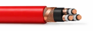

Medium Voltage VFD Motor Cable — 3GSEGCH / 3GSEGCY
Three-core EPR-insulated medium voltage VFD cable for fixed converter-to-motor connections. Select 3GSEGCH with a halogen-free polyolefin sheath or 3GSEGCY with a PVC sheath, with separate power-frequency and converter operating conditions.
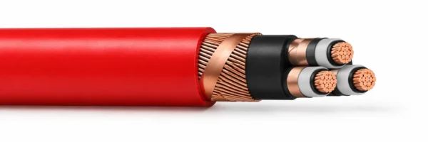
Medium voltage VFD cable connects a frequency converter to an AC motor through three EPR-insulated power cores, individual copper-tape screens and an overall copper screen. The 3GSEGCH and 3GSEGCY designs share this screened motor-supply arrangement, with different outer-sheath materials and installation conditions. Conductor sizes from 35 to 300 mm² remain together in the selection tables.
Choose the electrical operating condition before selecting the conductor size. The power-frequency rating is 6/10 kV at 50 Hz, while converter operation uses a separate 3.6/6 kV basis. The stated converter envelope also identifies a maximum link voltage, a fundamental voltage and a peak limit including harmonics. These values describe different parts of the drive waveform and should be checked against the converter output and motor insulation system.
Choose the sheath to suit the route. The halogen-free 3GSEGCH construction uses an ST8 polyolefin sheath and is intended for fixed installation away from direct burial and water installation. The PVC-sheathed 3GSEGCY construction permits direct burial, with continuous use in water excluded. Both designs have a red outer surface, black inner covering and numerical core identification.
Provide the converter waveform, motor voltage, conductor size, cable length and termination arrangement with the enquiry. Check the screen connection, gland space, pulling force and available fixed bend radius together. The current references apply to one cable at 40°C ambient; the installed route and grouping determine the final current selection.
Explore the industrial cable range for related configurations.
For low-voltage converter-fed motor drive circuits requiring symmetrical EMC screening, compare these VFD cable constructions: 2XSLCYK-J 0.6/1 kV XLPE VFD Motor Cable (for 0.6/1 kV XLPE-insulated motor feeders with low mutual capacitance and dual copper tape or braid screening); 2YSLCYK-JB 0.6/1 kV Symmetrical VFD Cable (for 0.6/1 kV symmetrical 3+3 core VFD motor leads with split protective earth conductors). Verify rated drive voltage, dV/dt impulse stress, and screen transfer impedance before ordering.
Construction
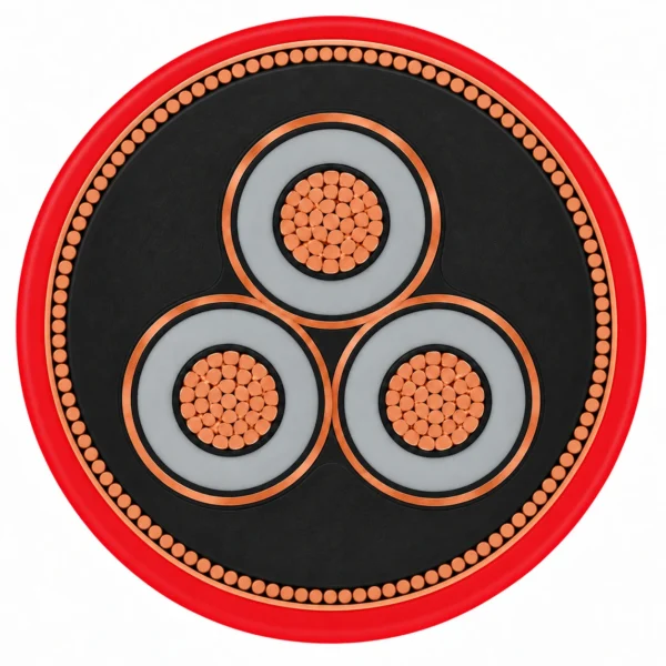
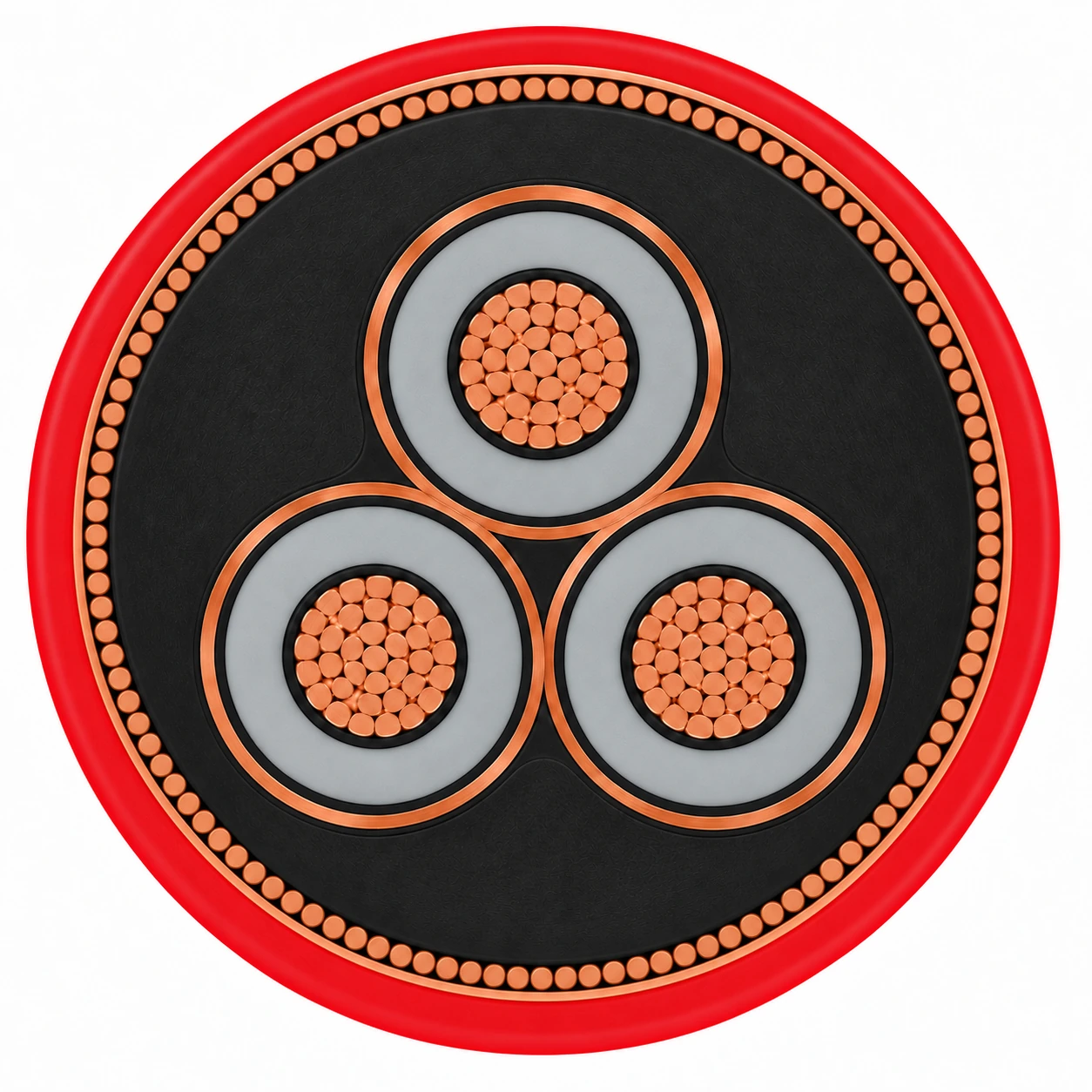
The representative 3GSEGCH 3 × 50 mm² construction has three round stranded copper conductors arranged as a compact triangle. Each EPR-insulated core has semiconductive field-control layers and copper-tape screening; the assembled cores have a black inner covering, an overall copper-wire screen and a red polyolefin sheath.
| Component | Material and construction |
|---|---|
| Phase conductors | Three round stranded copper conductors to IEC 60228 class 2. Class 5 construction is a separate request option. |
| Conductor and insulation screens | Inner and outer layers of semiconductive rubber compound around each EPR dielectric. |
| Core insulation and identification | EPR according to IEC 60502-2; numerical 1-2-3 identification printed on the outer semiconductive layer. |
| Individual metallic screens | Two copper tapes around each insulated core. The combined cross-section of all individual core screens is 16 mm² for 35–120 mm² phase conductors and 25 mm² above 120 mm². |
| Inner covering | Black polyolefin compound according to IEC 60502-2. |
| Overall metallic screen | Plain copper wires with a transverse helical copper tape. Electrical screen cross-section is approximately 0.5 times the phase-conductor cross-section. |
| 3GSEGCH outer sheath | Red ST8 polyolefin compound, flame retardant, low smoke and halogen free. |
| 3GSEGCY outer sheath | Red ST2 PVC compound; retain the separate installation and flame-test conditions of this construction. |
Applications
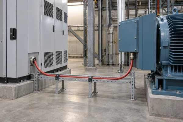
Select these screened three-core constructions for fixed medium voltage converter-to-motor power connections. Coordinate the cable insulation, screen termination and installation route with the drive system.
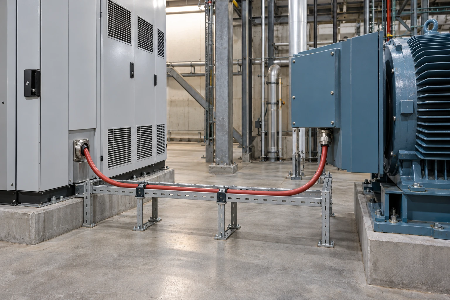
- Fixed connections between medium voltage frequency converters and AC motors in industrial drive systems.
- Indoor or outdoor fixed routes in dry, damp and wet surroundings, subject to the selected sheath and installation method.
- 3GSEGCH routes where a low-smoke halogen-free sheath is specified; install away from direct burial and water installation.
- 3GSEGCY routes that require a PVC sheath and permit direct burial; continuous use in water is excluded.
- Motor and converter terminations designed for the individual core screens and the common copper-wire screen.
- Use the selected fixed bend radius and pulling-force limit; the free-movement references do not define a continuous reeling or drag-chain duty.
For VFD motor drive engineering references and heavy-duty mining inverter feeders, consult these resources: What Is VFD Cable? Insulation, Grounds and Shield Explained (covering XLPE/EPR dielectric stress, symmetrical ground geometry, and high-frequency common-mode current containment); Mining VFD Cable 2000 V — 3 Power + 3 Ground + Ground Check (for 2000 V trailing and reeling mining inverter drives with three symmetrical grounds and a ground-check pilot). Confirm harmonic current derating, gland earthing termination, and installation bend radius.
Specifications
| Parameter | Value |
|---|---|
| Rated voltage, 50 Hz three-phase AC | U₀/U = 6/10 kV; maximum system voltage 12 kV. |
| Rated voltage, converter operation | U₀/U = 3.6/6 kV; maximum system voltage 7.2 kV. |
| Converter waveform envelope | Maximum link voltage 6.8 kV; fundamental voltage 4.16 kV; maximum peak voltage 15 kV including harmonics. |
| Phase conductor range | 3 × 35 to 3 × 300 mm²; round stranded copper, IEC 60228 class 2. |
| Conductor temperature limits | 90°C maximum operating temperature; 250°C maximum short-circuit temperature. |
| Installation temperatures | Fixed installation ambient minimum −30°C; laying temperature minimum −10°C. |
| Maximum conductor tensile load | 50 N/mm²; configuration-specific total pulling limits are listed below. |
| Sheath selection | 3GSEGCH: halogen-free ST8 polyolefin; 3GSEGCY: ST2 PVC. |
| Model and conductor configuration | Diameter over overall screen (mm) | Max. overall diameter (mm) | Min. fixed bend radius (mm) | Approx. mass (kg/km) | Max. tensile force (N) | Reference current at 40°C ambient (A) |
|---|---|---|---|---|---|---|
| 3GSEGCH 3 × 35 mm² | 41 | 45.5 | 364 | 3500 | 5250 | 154 |
| 3GSEGCH 3 × 50 mm² | 43.5 | 48 | 384 | 4200 | 7500 | 185 |
| 3GSEGCH 3 × 70 mm² | 47.5 | 52.5 | 420 | 5200 | 10500 | 230 |
| 3GSEGCH 3 × 95 mm² | 51.5 | 56.5 | 452 | 6400 | 14250 | 279 |
| 3GSEGCH 3 × 120 mm² | 54.5 | 60 | 480 | 7600 | 18000 | 321 |
| 3GSEGCH 3 × 150 mm² | 58 | 64 | 512 | 8700 | 22500 | 364 |
| 3GSEGCH 3 × 185 mm² | 62.5 | 68 | 544 | 10500 | 27750 | 417 |
| 3GSEGCH 3 × 240 mm² | 67.5 | 73.5 | 588 | 13000 | 36000 | 491 |
| 3GSEGCH 3 × 300 mm² | 72.7 | 78.1 | 594 | 15400 | 45000 | 569 |
| Model and conductor configuration | Diameter over overall screen (mm) | Max. overall diameter (mm) | Min. fixed bend radius (mm) | Free-movement bend reference (mm) | Approx. mass (kg/km) | Max. tensile force (N) | Reference current at 40°C ambient (A) | Reference conductor short-circuit current (kA) |
|---|---|---|---|---|---|---|---|---|
| 3GSEGCY 3 × 35 mm² | 41 | 45.5 | 364 | 683 | 3500 | 5250 | 154 | 5.57 |
| 3GSEGCY 3 × 50 mm² | 43.5 | 48 | 384 | 720 | 4200 | 7500 | 185 | 7.95 |
| 3GSEGCY 3 × 70 mm² | 47.5 | 52.5 | 420 | 788 | 5200 | 10500 | 230 | 11.13 |
| 3GSEGCY 3 × 95 mm² | 51.5 | 56.5 | 452 | On enquiry | 6400 | 14250 | 279 | 15.11 |
| 3GSEGCY 3 × 120 mm² | 54.5 | 60 | 480 | 900 | 7600 | 18000 | 321 | 19.08 |
| 3GSEGCY 3 × 150 mm² | 58 | 64 | 512 | 960 | 8700 | 22500 | 364 | 23.85 |
| 3GSEGCY 3 × 185 mm² | 62.5 | 68 | 544 | 1020 | 10500 | 27750 | 417 | 29.42 |
| 3GSEGCY 3 × 240 mm² | 67.5 | 73.5 | 588 | 1103 | 13000 | 36000 | 491 | 38.16 |
| 3GSEGCY 3 × 300 mm² | 72.7 | 78.1 | 594 | 1172 | 15400 | 45000 | 569 | 47.7 |
| Operating condition | U₀/U or fundamental voltage | Maximum system or link voltage | Peak condition |
|---|---|---|---|
| Three-phase AC at 50 Hz | 6/10 kV | 12 kV maximum system voltage | Coordinate with the power-frequency system design |
| Frequency-converter operation | 3.6/6 kV | 7.2 kV maximum system voltage | Coordinate with the converter output waveform |
| Converter operation including harmonics | 4.16 kV fundamental | 6.8 kV maximum link voltage | 15 kV maximum peak |
| Model | Outer sheath | Direct burial | Water installation | Flame and smoke references |
|---|---|---|---|---|
| 3GSEGCH | Red ST8 polyolefin | Excluded | Excluded | IEC 60332-1-2; IEC 60332-3-22; IEC 61034; IEC 60754-2 |
| 3GSEGCY | Red ST2 PVC | Permitted | Continuous use excluded | IEC 60332-1-2 |
The current values are references for one cable touching supporting surfaces at 40°C ambient. Apply the installation method, grouping and thermal conditions to the final current calculation.
3GSEGCH current references follow VDE 0298 part 4. For 3GSEGCY direct burial, determine the installed current according to the ground-installation conditions and DIN VDE 0276-620 6C.
The 3GSEGCY short-circuit current figures retain their conductor-size references. Coordinate protection and fault-clearing duration with the conductor thermal limit.
Power-frequency, converter fundamental, link and peak voltages are separate selection conditions. Include the complete drive waveform and termination requirements with the enquiry.
Configuration dimensions, bend radii, masses and tensile-force values belong to their own model rows. Select the sheath and installation route before applying them.
Standards
| Standard or specification | Application |
|---|---|
| IEC 60502-2 | EPR-insulated medium voltage cable design reference for both constructions. |
| IEC 60228 class 2 | Round stranded copper phase conductors; class 5 is a separate requested construction. |
| IEC 60502-1, ST8 | Polyolefin outer-sheath compound reference for 3GSEGCH. |
| IEC 60502-2, ST2 | PVC outer-sheath compound reference for 3GSEGCY. |
| IEC 60332-1-2 | Flame propagation test reference for both sheath constructions. |
| IEC 60332-3-22 / IEC 61034 / IEC 60754-2 | 3GSEGCH grouped-flame, smoke-emission and combustion-gas references. |
| DIN EN 55011 / DIN 0875 part 11 | EMC design reference, classes A1 and B1; coordinate screen connections with the equipment installation. |
| VDE 0298 part 4 / DIN VDE 0276-620 6C | Current-reference and ground-installation calculation references under the respective stated conditions. |
Related cable options
Compare these cable options by service combination, movement, load, voltage and transmission requirement.
2XSLCYK-J 0.6/1 kV XLPE VFD Motor Cable
A related cable option for a different application or duty profile.
View product
2YSLCYK-JB 0.6/1 kV Symmetrical VFD Cable
A related cable option for a different application or duty profile.
View product
RG7H1OR Three-Core HEPR Insulated MV Cable
A related cable option for a different application or duty profile.
View productRequest a cable recommendation and quotation
Send the required services, cable length, mechanical duty, environment, termination and quantity. Our team will review the application before quoting.
- Include the product name or SKU plus the required cable length and quantity.
- Attach a specification, drawing or data sheet when available.