








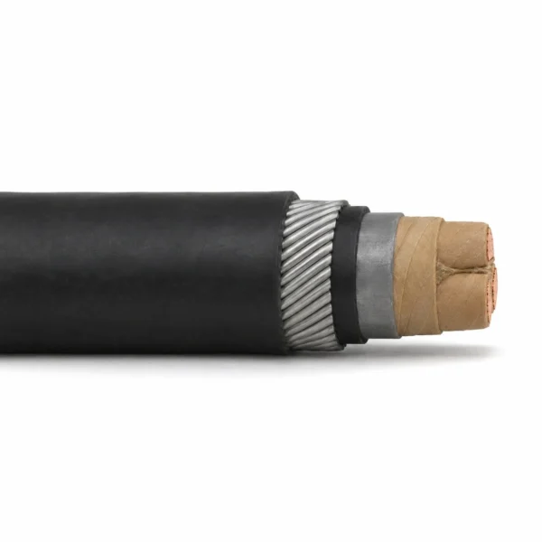
AS/NZS 1972 Paper-Insulated Mine Feeder Cable, 11/11 kV
Three-core 11/11 kV paper-insulated mine feeder cable for fixed distribution and specified replacement work. Sector-shaped copper conductors, individual paper insulation, a common paper belt, lead sheath, PVC bedding, galvanized steel-wire armour and PVC outer sheath form the PILC construction.
Paper-insulated mine feeder cable at 11/11 kV is a three-core, lead-sheathed and steel-wire-armoured construction for fixed mine distribution. Its sector-shaped copper conductors have individual paper-tape insulation, with jute fillers and a common paper-tape belt beneath the lead sheath. PVC bedding separates the lead from the galvanized steel-wire armour, and a PVC outer sheath completes the cable.
This PILC construction is relevant when a project specifies paper insulation or an existing feeder must be replaced within an established cable and termination system. Retain the full 11/11 kV designation when submitting the enquiry. Conductor area alone does not identify a compatible replacement: the lead-sheath dimensions, armour, insulation arrangement, cable entry and jointing details must also match the installation.
Two separate dimensional schedules cover discrete conductor sizes. Schedule 1 includes 25–400 mm²; schedule 2 includes 50–400 mm² and provides additional layer diameters and electrical reference data. Their outer diameters and masses differ, so select a complete schedule rather than combining values. For a change to XLPE or EPR insulation, compare XLPE/PVC MP-GC feeder cable or EPR/CPE MP-GC feeder cable, and assess the voltage, feeder construction and termination system separately.
Provide the existing cable marking, conductor size, route, joint or termination details and required length for a technical quotation. TEBAOFLEX supplies this paper-insulated feeder family from a 50 m minimum order quantity, with a manufacturing lead time of 7–45 working days. State the applicable standard edition, inspection requirements and acceptance documents with the enquiry so the ordered build can be defined clearly.
For low-voltage 0.6/1 kV and 1.8/3 kV fixed underground coal mine distribution roadways specifying 70 °C flame-retardant PVC insulation and double steel-tape armour under MT/T 818.12 (MVV and MVV22), see: MVV & MVV22 (0.6/1–1.8/3 kV) PVC Insulated & Steel-Tape Armoured Underground Mine Power Cable (MT/T 818.12).
Explore the mining and tunneling cable range for related configurations.
Construction
Three sector-shaped copper cores are paper insulated and assembled with jute fillers inside a common paper belt and lead sheath. The main image represents PILC 11/11 kV 3 × 95 mm² from dimensional schedule 2.
| Component | Material and construction |
|---|---|
| Conductors | Three sector-shaped stranded plain-copper conductors; the detailed schedule 2 construction specifies annealed copper. |
| Individual core insulation | Paper tape around each sector-shaped conductor. |
| Fillers | Jute fillers within the three-core assembly. |
| Belt insulation | Common paper-tape insulation surrounding the filled core assembly. |
| Metallic sheath | One continuous lead sheath around the complete insulated assembly. |
| Bedding | PVC bedding outside the lead sheath. |
| Armour | One common layer of galvanized round steel wires over the PVC bedding. |
| Outer sheath | PVC outer sheath; AS/NZS 1026 is the referenced paper-insulated cable construction standard. |
Applications
Select this paper/lead construction for fixed mine feeders and documented replacement projects requiring the 11/11 kV PILC insulation and sheathing arrangement.
- Stationary high-voltage mine distribution where paper-insulated, lead-sheathed cable is specified.
- Replacement of identified 11/11 kV PILC feeders after checking the existing cable construction, jointing system and terminations.
- Projects requiring sector-shaped copper conductors, a common lead sheath and galvanized steel-wire armour.
- Fixed supported routes with a defined pulling plan, bend requirements, sheath integrity checks and bonding design.
For route and construction selection, see the medium-voltage mining cable selection guide.
For a low-voltage fixed mine-distribution circuit, compare Type A and Type B 1.1/1.1 kV feeder cable. It uses a different voltage and insulation arrangement from this paper-insulated 11/11 kV construction.
Specifications
| Parameter | Value |
|---|---|
| Rated voltage U₀/U | 11/11 kV |
| Power-core count and shape | Three sector-shaped copper power cores |
| Insulation | Individual paper tape plus a common paper-tape belt |
| Sheath and armour | Lead sheath / PVC bedding / galvanized steel-wire armour / PVC outer sheath |
| Installation | Fixed mine feeder; specified PILC replacement work |
| Schedule 1 sizes | 25, 35, 50, 70, 95, 120, 150, 185, 240, 300 and 400 mm² |
| Schedule 2 sizes | 50, 70, 95, 120, 150, 185, 240, 300 and 400 mm² |
| Minimum insulation between conductors | 5.6 mm |
| Minimum insulation between conductors and lead sheath | 5.4 mm |
| Minimum order quantity | 50 m |
| Manufacturing lead time | 7–45 working days |
| Model and configuration | Conductor sizes | Construction selection | Procurement input |
|---|---|---|---|
| PILC 11/11 kV, three sector cores — schedule 1 | 25–400 mm², discrete sizes below | Use the complete schedule 1 lead/armour/sheath dimensions and mass. | Identify the existing cable and termination dimensions. |
| PILC 11/11 kV, three sector cores — schedule 2 | 50–400 mm², discrete sizes below | Use schedule 2 dimensions, layer diameters and its electrical reference data. | State the route, loading conditions, jointing system and acceptance tests. |
| Model and configuration | Min. insulation between conductors (mm) | Min. insulation to lead (mm) | Lead sheath (mm) | Armour wire (mm) | Outer sheath (mm) | Nominal OD (mm) | Nominal mass (kg/100 m) |
|---|---|---|---|---|---|---|---|
| PILC 11/11 kV 3 × 25 mm² | 5.6 | 5.4 | 1.8 | 2.5 | 2.4 | 47.9 | 630 |
| PILC 11/11 kV 3 × 35 mm² | 5.6 | 5.4 | 1.8 | 2.5 | 2.5 | 50.3 | 695 |
| PILC 11/11 kV 3 × 50 mm² | 5.6 | 5.4 | 1.8 | 2.5 | 2.5 | 50.1 | 725 |
| PILC 11/11 kV 3 × 70 mm² | 5.6 | 5.4 | 1.9 | 2.5 | 2.6 | 53.5 | 855 |
| PILC 11/11 kV 3 × 95 mm² | 5.6 | 5.4 | 2.0 | 2.5 | 2.6 | 57.2 | 1000 |
| PILC 11/11 kV 3 × 120 mm² | 5.6 | 5.4 | 2.0 | 2.5 | 2.7 | 60.1 | 1120 |
| PILC 11/11 kV 3 × 150 mm² | 5.6 | 5.4 | 2.1 | 2.5 | 2.8 | 63.0 | 1260 |
| PILC 11/11 kV 3 × 185 mm² | 5.6 | 5.4 | 2.3 | 3.15 | 2.9 | 68.0 | 1540 |
| PILC 11/11 kV 3 × 240 mm² | 5.6 | 5.4 | 2.4 | 3.15 | 3.0 | 73.1 | 1820 |
| PILC 11/11 kV 3 × 300 mm² | 5.6 | 5.4 | 2.6 | 3.15 | 3.2 | 77.9 | 2120 |
| PILC 11/11 kV 3 × 400 mm² | 5.6 | 5.4 | 2.7 | 3.15 | 3.4 | 83.5 | 2500 |
| Model and configuration | Min. insulation between conductors (mm) | Min. insulation to lead (mm) | Lead sheath (mm) | Armour wire (mm) | Outer sheath (mm) | Nominal OD (mm) | Approx. mass (kg/100 m) |
|---|---|---|---|---|---|---|---|
| PILC 11/11 kV 3 × 50 mm² | 5.6 | 5.4 | 1.8 | 2.50 | 2.5 | 50.6 | 776 |
| PILC 11/11 kV 3 × 70 mm² | 5.6 | 5.4 | 1.9 | 2.50 | 2.6 | 54.0 | 915 |
| PILC 11/11 kV 3 × 95 mm² | 5.6 | 5.4 | 2.0 | 2.50 | 2.6 | 57.7 | 1070 |
| PILC 11/11 kV 3 × 120 mm² | 5.6 | 5.4 | 2.0 | 2.50 | 2.7 | 60.6 | 1198 |
| PILC 11/11 kV 3 × 150 mm² | 5.6 | 5.4 | 2.1 | 2.50 | 2.8 | 63.5 | 1348 |
| PILC 11/11 kV 3 × 185 mm² | 5.6 | 5.4 | 2.3 | 3.15 | 2.9 | 68.5 | 1648 |
| PILC 11/11 kV 3 × 240 mm² | 5.6 | 5.4 | 2.4 | 3.15 | 3.0 | 73.6 | 1947 |
| PILC 11/11 kV 3 × 300 mm² | 5.6 | 5.4 | 2.6 | 3.15 | 3.2 | 78.4 | 2268 |
| PILC 11/11 kV 3 × 400 mm² | 5.6 | 5.4 | 2.7 | 3.15 | 3.4 | 84.0 | 2675 |
| Model and configuration | Over lead sheath (mm) | Over PVC bedding (mm) | Over armour (mm) |
|---|---|---|---|
| PILC 11/11 kV 3 × 50 mm² | 37.5 | 40.4 | 45.4 |
| PILC 11/11 kV 3 × 70 mm² | 40.7 | 43.6 | 48.6 |
| PILC 11/11 kV 3 × 95 mm² | 44 | 47.3 | 52.3 |
| PILC 11/11 kV 3 × 120 mm² | 46.7 | 50 | 55.0 |
| PILC 11/11 kV 3 × 150 mm² | 49.4 | 52.7 | 57.7 |
| PILC 11/11 kV 3 × 185 mm² | 52.9 | 56.2 | 62.5 |
| PILC 11/11 kV 3 × 240 mm² | 57.4 | 61.1 | 67.4 |
| PILC 11/11 kV 3 × 300 mm² | 61.8 | 65.5 | 71.8 |
| PILC 11/11 kV 3 × 400 mm² | 66.9 | 70.6 | 76.9 |
| Model and configuration | Max. DC resistance at 20°C (Ω/km) | Max. AC resistance at 65°C (Ω/km) |
|---|---|---|
| PILC 11/11 kV 3 × 50 mm² | 0.3870 | 0.4560 |
| PILC 11/11 kV 3 × 70 mm² | — | 0.3160 |
| PILC 11/11 kV 3 × 95 mm² | 0.1930 | 0.2280 |
| PILC 11/11 kV 3 × 120 mm² | 0.1530 | 0.1820 |
| PILC 11/11 kV 3 × 150 mm² | 0.1240 | 0.1480 |
| PILC 11/11 kV 3 × 185 mm² | 0.0991 | 0.1190 |
| PILC 11/11 kV 3 × 240 mm² | 0.0754 | 0.0919 |
| PILC 11/11 kV 3 × 300 mm² | 0.0601 | 0.0748 |
| PILC 11/11 kV 3 × 400 mm² | 0.0470 | 0.0606 |
| Model and configuration | Unenclosed, spaced (A) | Unenclosed, touching (A) |
|---|---|---|
| PILC 11/11 kV 3 × 50 mm² | 110 | 105 |
| PILC 11/11 kV 3 × 70 mm² | 135 | 125 |
| PILC 11/11 kV 3 × 95 mm² | 155 | 150 |
| PILC 11/11 kV 3 × 120 mm² | 175 | 165 |
| PILC 11/11 kV 3 × 150 mm² | 210 | 200 |
| PILC 11/11 kV 3 × 185 mm² | 240 | 230 |
| PILC 11/11 kV 3 × 240 mm² | 290 | 275 |
| PILC 11/11 kV 3 × 300 mm² | 320 | 300 |
| PILC 11/11 kV 3 × 400 mm² | 365 | 345 |
Schedules 1 and 2 are separate reference constructions. Select a complete schedule; the same conductor area has different outer diameters and masses in the two schedules.
The 5.6 mm minimum is insulation between conductors; the 5.4 mm minimum is between conductors and the lead sheath. Neither value is the radial thickness of paper insulation on a single core.
Mass is expressed in kg/100 m. Diameters and masses are reference values subject to the selected construction and manufacturing tolerances.
In schedule 1, the nominal 35 mm² and 50 mm² overall diameters are 50.3 mm and 50.1 mm respectively. Use the specific row and agreed order drawing for cable-entry selection; do not interpolate the diameter from conductor area.
A dash in the 70 mm² DC-resistance cell means no value is assigned in this reference table. Obtain the conductor resistance requirement with the order-specific test schedule.
Schedule 2 current figures distinguish unenclosed spaced and unenclosed touching arrangements. They are conditional reference values, not a universal cable rating: calculate the ordered circuit for its ambient temperature, spacing, grouping, installation and thermal conditions.
The 65°C reference attached to AC resistance is a measurement/calculation condition, not an independently stated ambient or installation-temperature limit.
Confirm bend radius, pulling method, lead-sheath handling, sealing, earthing and joint compatibility for the selected route. This fixed feeder has no assigned trailing, continuous-reeling or unsupported-shaft rating.
Standards
| Standard or specification | Application |
|---|---|
| AS/NZS 1972:2006 | Fixed mine-feeder construction reference, other than reeling and trailing cables. |
| AS/NZS 1026 | Impregnated-paper-insulated cable construction reference; the official record identifies the 2004 edition. |
| AS/NZS 1125 | Conductor reference listed with dimensional schedule 1. |
| AS/NZS 3808 | Insulating and sheathing material reference listed with dimensional schedule 1. |
Official standards and approval references
AS/NZS 1972:2006 is the edition associated with these fixed-feeder constructions. The official 2026 review record identifies the 2006 designation; the review year is not a new cable-standard edition.
- Standards New Zealand — AS/NZS 1972:2006 official review record — Official record identifying the underground-coal-mine cable standard for constructions other than reeling and trailing cables.
- Standards New Zealand — AS/NZS 1026:2004 paper-insulated cable reference — Official record identifying the impregnated-paper cable standard for working voltages up to and including 19/33 (36) kV.
Certifications and document support
Review our company certificates and document scopes when identifying the documentation required for the quoted construction.
Specify the 11/11 kV PILC construction, conductor size, lead and armour dimensions, installation conditions and required acceptance tests. Match product-specific approval or test documents to the ordered paper/lead build. Standard references and company management-system records do not replace the project’s required product documents.
Related cable options
Compare these cable options by service combination, movement, load, voltage and transmission requirement.
Type MP-GC 15kV Mine Power Feeder Cable
A related cable option for a different application or duty profile.
View product
Type A and Type B 1.1/1.1 kV Mine Feeder Cable — AS/NZS 1972
A related cable option for a different application or duty profile.
View productRequest a cable recommendation and quotation
Send the required services, cable length, mechanical duty, environment, termination and quantity. Our team will review the application before quoting.
- Include the product name or SKU plus the required cable length and quantity.
- Attach a specification, drawing or data sheet when available.