


Mining Cable Movement Guide
Use a reeling cable when a powered drum repeatedly winds and pays out the cable. Use a trailing cable when the cable follows the machine, is dragged or is repositioned along the route without routine powered-drum cycling. The labels describe different mechanical duties, so equal voltage and conductor size do not make the cables interchangeable.
Drum cycle, trailing route or both.
Bending, tension, torsion and contact.
Load, protection, screen and pilot.
Data sheet, tests and approval path.
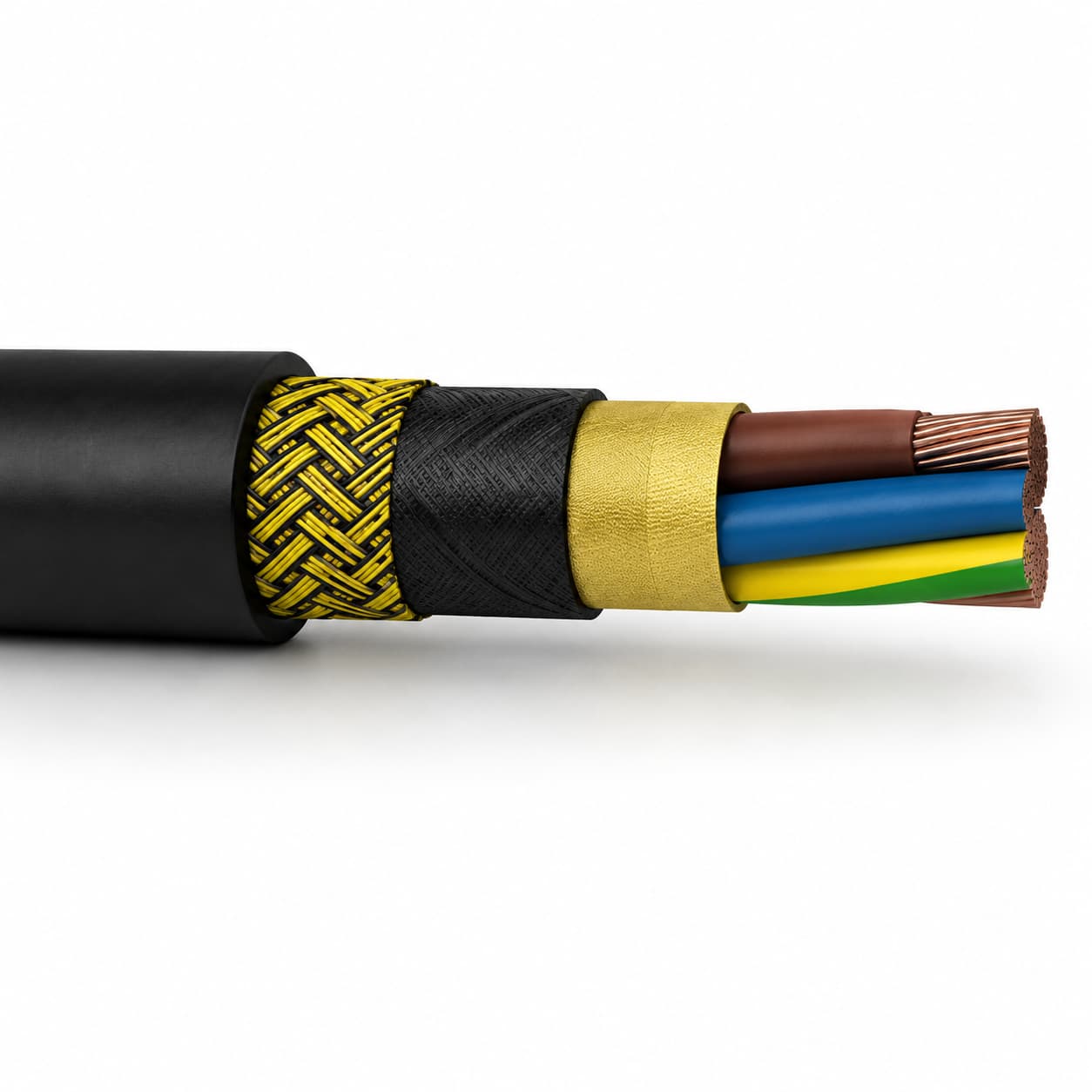
Reeling cable vs trailing cable: the quick decision
The movement pattern is the first filter. Reeling duty creates repeated drum bending, tension, layer pressure, guide contact and possible torsion. Trailing duty puts more emphasis on dragging, impact, crushing, route crossings, pulling and irregular bends.
WorkSafe Western Australia defines a reeling cable as one designed to be frequently reeled on and off a drum, while a trailing cable is designed to move with mobile apparatus. That distinction is a useful engineering starting point even when another jurisdiction governs the project.
| Decision factor | Reeling cable | Trailing cable |
|---|---|---|
| Primary movement | Repeated winding and payout on a powered drum | Follows, drags or is repositioned with the machine |
| Dominant mechanical inputs | Dynamic bending, tension, torsion, side pressure and acceleration | Abrasion, impact, crushing, pulling, crossings and irregular bends |
| Essential equipment data | Drum geometry, cable layers, speed, guides, fleet angle and anchoring | Route surface, travel, pull method, cable handler, crossings and protection |
| Thermal question | How much energized cable remains wound, and in how many layers? | How is the cable laid, grouped, covered or exposed along the route? |
| Construction priority | Stable geometry and controlled load transfer through the repeated reel cycle | Flexible movement plus protection against the actual ground-contact hazards |
| Common mistake | Using installed bend radius as proof of dynamic reel suitability | Assuming a flexible jacket makes the cable suitable for every drag route |
| Approval rule | Validate the exact construction, electrical system, accessories and governing requirements for the application | |
What changes inside a reeling or trailing cable?
There is no universal layer recipe for either label. Voltage, standard, mine type and machine design change the conductor, insulation, screens, earth or pilot cores, reinforcement and outer jacket. The comparison below describes design priorities to verify, not a promise that every cable contains the same features.
| Cable element | Reeling-duty question | Trailing-duty question |
|---|---|---|
| Flexible conductors | Can the stranding and lay tolerate the specified dynamic bend cycle under tension? | Can the conductor system tolerate the stated movement and irregular route bends? |
| Core lay and fillers | How is cable geometry kept stable as the cable enters, leaves and reverses on the drum? | How are cores supported during pulling, dragging, impact and route changes? |
| Support or reinforcement | Is a central support, braid or other tensile/anti-torsion element required, and how is it terminated? | Is reinforcement needed for the pull method, hanging length, handler or local mechanical loads? |
| Insulation and screens | Do the electrical layers match the voltage, protection system, fault duty, termination and repeated movement? | |
| Outer jacket | Does the complete jacket system suit reel, roller and guide contact as well as oil, water, UV and temperature exposure? | Does it suit abrasion, cuts, crushing, mud, water, oil, chemicals, sunlight and the route surface? |
A material name alone is not a selection. Jacket thickness, reinforcement, bonding, conductor lay, cable diameter and the complete tested construction determine how the cable behaves in service.
Where abrasion is the dominant exposure rather than one factor among several, abrasion-resistant jacket selection for mobile equipment works through the compounds, the test methods and the route conditions that decide how long a sheath survives reel and drag contact.
When should you specify a mining reeling cable?
Start with a reeling family when the cable repeatedly winds onto and pays off a powered drum during normal machine travel. Typical applications include load-haul-dump (LHD) machines, electric shovels, excavators, stackers, reclaimers and other reel-fed mobile equipment.
The NSHTOEU 0.6/1 kV LHD reeling cable record shows a low-voltage example with bonded anti-torsion reinforcement and an optional central support path. The R-(N)TSCGEWÖU medium-voltage reeling cable record provides a separate MV product path. These links are starting points, not proof that one listed construction fits a particular drum.
- Define whether the drum is monospiral, cylindrical or multilayer.
- Provide core diameter, flange diameter, drum width, groove data and cable capacity.
- State travel distance, cycles, speed, acceleration, slope and dwell conditions.
- Identify guides, rollers, cable entry, reverse bends, fleet angle and hanging length.
- State maximum pull, torque control and how any support element is anchored.
When should you specify a mining trailing cable?
Start with a trailing family when the cable moves with the machine but is not routinely stored by a powered reel. It may be dragged, laid out, repositioned, picked up by a cable handler or moved between protected route positions.
The NTSWÖU-J 0.6/1 kV trailing cable record is one low-voltage product reference. For a semi-flexible MV route such as a conveyor or pump connection, the F-(N)TSCGEWÖU medium-voltage cable record illustrates an adjacent application path. A semi-flexible cable should not be relabeled as a powered-reel cable without specific validation.
- Map every surface: rock, mud, concrete, rails, trays, ramps and standing water.
- Mark vehicle crossings, sharp edges, pinch points, doors, guides and heat sources.
- Describe the pulling method, maximum travel, direction changes and handling equipment.
- Define strain relief, couplers, junctions, clamps, route protection and inspection access.
- Record the damage modes already seen instead of asking only for a tougher jacket.
What if the cable uses a handler or storage reel?
Describe every movement zone. A cable can trail across part of the route, reverse-bend through a handler and then sit on a reel used only for relocation. A storage reel does not automatically create reeling duty, while a handler can create repeated bending and tension even when the cable never reaches a drum. A route with no movement zone at all is a static duty, covered separately in fixed and armoured mine routes.
Consider two cables with the same voltage and conductor area. One lies out before the machine starts; the other passes through an S-bend handler throughout every shift. Their electrical labels match, but the second application makes reverse-bend geometry, guide pressure, pulling control and fatigue central to the specification. The movement description, not the nearest product name, resolves the grey area.
Seven reel and dynamic-bend inputs to verify
A reel does not read the data sheet; it responds to diameter, tension, speed, alignment and the amount of cable stored. Supply these inputs before a manufacturer confirms reeling suitability.
Use the exact minimum and maximum outside diameter for grooves, guides, clamps, entries and reel capacity.
Give core and flange diameters, width, groove profile, winding direction and number of stored layers.
List the drum, sheaves, rollers, S-bends and every point where the cable reverses direction.
State travel, cycles, speed, acceleration, braking, dwell time and ambient or cable temperature.
Provide pulling tension, hanging length, slope, torsion, side pressure and control method.
State whether the cable remains energized while wound and how many layers are stored under load.
Show how conductors, earths, pilots, screens and any support element are terminated and strain-relieved.
Trailing-cable hazards need route controls, not only cable changes
Abrasion resistance cannot compensate for an unmanaged vehicle crossing or a sharp steel edge. Route design, separation, supports, visible markers, crossing protection, strain relief, inspection and handling rules form part of the cable system.
For Western Australian mines, WorkSafe guidance calls for cables to be located, supported and protected to reduce damage, avoid obstructing access and separate them from other services. In US underground coal mines, 30 CFR Part 75, Subpart G covers topics including flame resistance, circuit protection, splices, clamping, protection from mechanical damage and disconnection. Apply only the rules and editions that govern the actual mine.
Electrical checks shared by reeling and trailing cables
Movement duty does not replace the electrical design. Confirm system voltage, load current, starting duty, cable length, voltage drop, installation and thermal conditions, fault level, protection settings, conductor area, screens, earth conductors, pilot or ground-check function, couplers, glands and termination kits.
Do not confuse a grounding conductor with a pilot or ground-check conductor. The grounding conductor provides the equipment-grounding path. In systems that use earth-continuity monitoring, a pilot core forms part of a monitoring loop that can initiate de-energization when the circuit moves outside its accepted state. WorkSafe WA explains this function in its regulatory context; the project schematic and local rules determine the required arrangement.
Standards also depend on the market and mine. For example, WorkSafe WA cites AS/NZS 2802:2000 for mining/general use other than underground coal and discusses AS/NZS 1802:2018 in underground-coal cable context. Name the required standard, edition and any mine-specific acceptance documents in the RFQ.
A practical reeling or trailing cable selection process
Separate powered reeling, free trailing, handler bends, hanging sections and storage-only reel use.
Confirm voltage, current, starting duty, length, voltage drop, thermal condition, protection and fault requirements.
Record bend geometry, tension, torsion, speed, cycles, pull method, crossings, crushing and impact.
State water, mud, oil, chemicals, UV, ozone, flame requirements and operating temperatures.
Confirm earth, pilot or ground-check, screens, relays, couplers, glands, clamps and strain relief.
Give the jurisdiction, standard edition, test plan, marking, inspection and acceptance requirements.
Review the cross-section, dimensions, bend data, accessories, deviations and machine compatibility before approval.
RFQ data for a reeling or trailing mining cable
Send enough application data for the supplier to evaluate a construction rather than guess from a cable name.
- Electrical: system voltage, current or conductor area, phases/cores, cable length, starting duty, voltage-drop limit, fault and protection data.
- Movement: machine, travel, reel/handler type, drum and roller drawing, bend radii, speed, cycles, tension, torsion, hanging length and stored layers.
- Route and environment: surfaces, crossings, crushing/impact exposure, water, oil, chemicals, sunlight, flame requirement and temperatures.
- System interfaces: screens, earth and pilot functions, couplers, glands, termination, clamps, strain relief and support-element anchoring.
- Commercial documents: standard and edition, cable marking, test/inspection plan, required approvals, drum length, quantity and delivery country.
Send the completed movement and electrical schedule for a technical quotation review. Final cable approval remains with the responsible engineer and applicable authority.
Frequently asked questions
Can a trailing cable be used on a powered reel?
Not by default. The supplier and responsible engineer should confirm the exact construction against drum diameter, layers, dynamic bend radius, speed, tension, torsion, thermal condition and termination before approving powered-reel duty.
Is a reeling cable stronger than a trailing cable?
Not in every way. A reeling cable is designed around repeated drum movement, while a trailing cable is selected around its route and handling hazards. Suitability depends on the complete construction and application, not a universal strength ranking.
Does minimum bend radius prove that a cable is suitable for reeling?
No. A fixed or installation bend limit does not by itself cover repeated dynamic bending under tension. Request the dynamic limit and operating conditions for the exact cable and reel system.
What if the machine uses a cable handler?
Describe every guide, reverse bend, pull and storage zone. A handler can impose repeated bending, side pressure and tension even when the cable is not stored on a powered drum.
What information matters most in a reeling or trailing cable RFQ?
Provide the electrical system, machine, complete movement cycle, bend or reel geometry, tension, route hazards, environment, protection and pilot functions, accessories, standard edition, tests, length and quantity.
Sources and editorial scope
This guide uses regulator and standards records for definitions and safety boundaries, government research for mechanism context, and current TEBAOFLEX records for product-specific examples. It is a selection aid, not an approval, certificate, engineering calculation or repair instruction.
- WorkSafe WA – trailing and reeling cable guidance
- Standards Australia – AS/NZS 2802:2000 catalog record
- Standards Australia – AS/NZS 1802:2018 catalog record
- 30 CFR Part 75, Subpart G – trailing cables
- Resources Safety and Health Queensland – surface trailing-cable management
- US Bureau of Mines/NIOSH archive – Cable Handling in Surface Mines
Related product references
Compare product data only after the movement and electrical system are defined.