


(N)TSCGEHXOEU 12/20–20/35 kV Wind Turbine Twist Cable
(N)TSCGEHXOEU medium-voltage wind turbine twist cable, with separate 12/20 kV three-core and 12/20–20/35 kV 3+3 catalogue configurations. Class 5 bare copper, HEPR insulation and halogen-free rubber sheaths are specified in the reference design.
(N)TSCGEHXOEU is a flexible medium-voltage power cable designation for wind-turbine routes that hang freely, twist with equipment movement or are installed fixed. The supplied design references cover 12/20 kV and 20/35 kV 3+3 configurations, plus a separate 12/20 kV three-core configuration. Each has its own outside diameter, bending, electrical and weight data; choose the formation before selecting a termination or planning tower clearance.
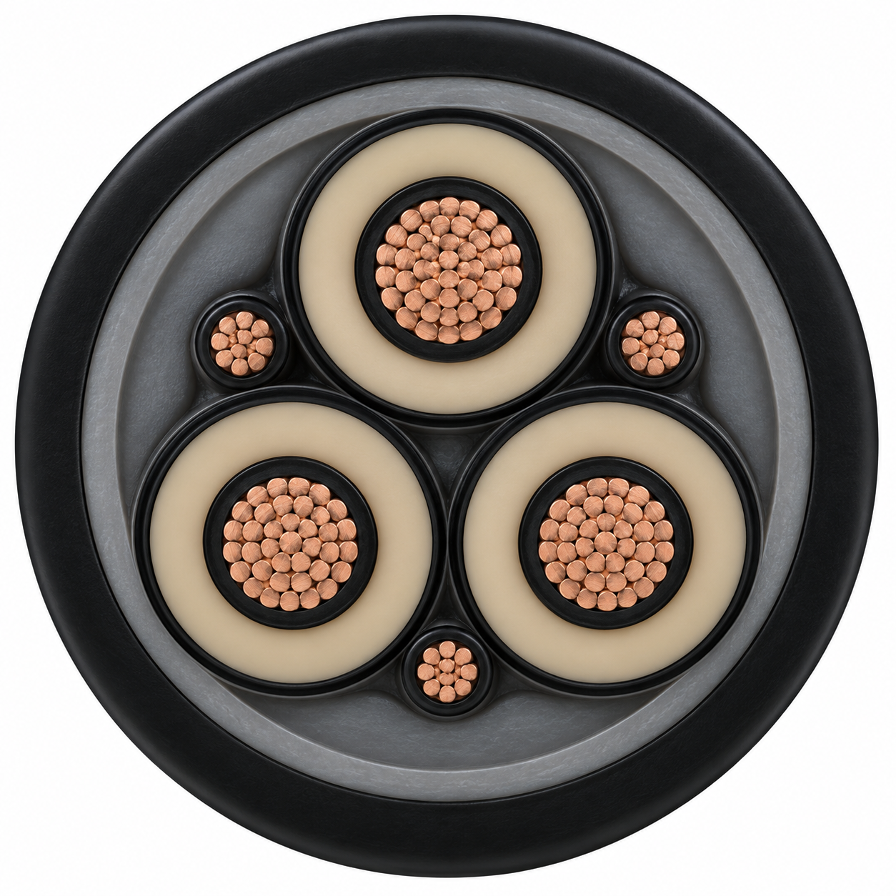
The referenced construction uses finely stranded Class 5 bare copper conductors, HEPR insulation with semiconductive field-control layers, a halogen-free GM1b inner sheath and a black halogen-free HXM1 outer sheath. It is intended for medium mechanical stress in wind turbines. A published ±100°/m torsional reference describes the catalogue design, while the allowable movement of an actual assembly depends on the selected size, unsupported length and termination layout.
Use the separate tables in Specifications to compare the exact model, rated voltage and core formation. Quotation inputs should include the turbine voltage, three-core or 3+3 formation, cross-section, free-hanging length, twist envelope, bend path, environment and required acceptance documents. For the higher voltage wind family, see the 36/60–69 kV (N)TSCGEHXOEU cable; for a single-core screened route, see 12/20 kV (N)TMCHXOEU. Browse the industrial cable range for adjacent duties.
Construction
The design reference uses fine-stranded, Class 5 bare copper conductors. The HEPR dielectric is bounded by inner and outer semiconductive rubber layers to control the electrical field. Natural core colouring with the black semiconductive layer is specified in the source.
| Property | Source catalogue reference |
|---|---|
| Conductor | Electrolytic bare copper, finely stranded Class 5 to IEC 60228 / DIN VDE 0295 |
| Insulation | Halogen-free, heat-resistant HEPR |
| Electrical field control | Inner and outer semiconductive rubber layers |
| Inner sheath | Halogen-free GM1b rubber compound |
| Outer sheath | Black halogen-free HXM1 compound |
| Configuration boundary | 3+3 and three-core configurations have separate published size tables |
The source lists no universal metallic-screen or armour arrangement for every row. Any required screen, bonding path and termination details should be confirmed against the released cable drawing for the selected configuration.
Applications
The reference design is intended for wind-turbine medium-voltage power transmission with medium mechanical stress. The catalogue permits free-moving, free-hanging and fixed installation, and identifies twistability for free-hanging operation. Validate torsional duty, cable support and bend path against the turbine layout before selecting a size.
Three-core or 3+3?
The 12/20 kV catalogue contains both 3+3 and three-core rows. They are not interchangeable dimension tables: for example, the 3+3 3×70+3×70/3 row and three-core 3×70/70 row share nominal phase size but have different documented masses and bend-radius values. Specify the full catalogue formation on the RFQ and electrical drawing.
A crane reeling cable follows a different winding duty. For that route, compare the NTSCGEWOEU medium-voltage crane reeling cable rather than selecting this wind-tower construction by voltage alone.

Specifications
Select voltage and exact core formation before comparing outside diameter, current, terminations or free-hanging geometry. The three source tables below are separate constructions; a 3+3 row must not be read as a plain three-core row.
| Property | Source catalogue reference |
|---|---|
| Type designation | (N)TSCGEHXOEU |
| Voltage options in this page | 12/20 kV and 20/35 kV (U0/U) |
| 12/20 kV maximum operating voltage, AC / DC | 13.9/24 kV / 18/36 kV |
| 20/35 kV maximum operating voltage, AC / DC | 24.2/42 kV / 31.5/63 kV |
| Main-core AC test voltage | 30 kV for 5 min at 12/20 kV; 50 kV for 5 min at 20/35 kV |
| Maximum conductor temperature / short-circuit temperature | 90°C / 250°C |
| Ambient temperature, fully flexible operation | −40°C to +80°C |
| Maximum tensile load on conductor | 15 N/mm² |
| Reference torsional stress | ±100°/m |
| Minimum bend radius | See size-specific free-moving bend-radius columns; DIN VDE 0298 Part 3 referenced |
12/20 kV, 3+3 configuration
| Model + source configuration | OD min–max (mm) | Free-moving bend radius min (mm) | Approx. weight (kg/km) | Conductor R20 max (Ω/km) | Capacitance (µF/km) | Reactance 50/60 Hz (Ω/km) | Ampacity (A) | 1 s short-circuit (kA) |
|---|---|---|---|---|---|---|---|---|
| (N)TSCGEHXOEU 12/20 kV 3×50+3×50/3 mm² | 50.5–53.5 | 535 | 4 090 | 0.386 | 0.293 | 0.103 / 0.124 | 192 | 7.15 |
| (N)TSCGEHXOEU 12/20 kV 3×70+3×35/3 mm² | 54–57.5 | 550 | 4 950 | 0.272 | 0.326 | 0.099 / 0.118 | 246 | 10.01 |
| (N)TSCGEHXOEU 12/20 kV 3×70+3×70/3 mm² | 58–62 | 570 | 5 660 | 0.272 | 0.326 | 0.099 / 0.118 | 246 | 10.01 |
| (N)TSCGEHXOEU 12/20 kV 3×95+3×50/3 mm² | 57–62 | 580 | 5 910 | 0.206 | 0.357 | 0.095 / 0.114 | 298 | 13.59 |
| (N)TSCGEHXOEU 12/20 kV 3×95+3×95/3 mm² | 57–62 | 610 | 5 970 | 0.206 | 0.357 | 0.095 / 0.114 | 298 | 13.59 |
| (N)TSCGEHXOEU 12/20 kV 3×120+3×70/3 mm² | 61–68 | 650 | 7 260 | 0.158 | 0.369 | 0.088 / 0.105 | 346 | 17.17 |
| (N)TSCGEHXOEU 12/20 kV 3×240+3×120/3 mm² | 74–81.5 | 780 | 12 300 | 0.078 | 0.480 | 0.081 / 0.098 | 538 | 34.34 |
20/35 kV, 3+3 configuration
| Model + source configuration | OD min–max (mm) | Free-moving bend radius min (mm) | Approx. weight (kg/km) | Conductor R20 max (Ω/km) | Capacitance (µF/km) | Reactance 50/60 Hz (Ω/km) | Ampacity (A) | 1 s short-circuit (kA) |
|---|---|---|---|---|---|---|---|---|
| (N)TSCGEHXOEU 20/35 kV 3×35+3×35/3 mm² | 57.6–60.6 | 606 | 4 380 | 0.549 | 0.189 | 0.122 / 0.146 | 158 | 5.01 |
| (N)TSCGEHXOEU 20/35 kV 3×50+3×25/3 mm² | 62–65.8 | 650 | 5 200 | 0.386 | 0.188 | 0.115 / 0.138 | 192 | 7.15 |
| (N)TSCGEHXOEU 20/35 kV 3×50+3×50/3 mm² | 62.8–65.8 | 658 | 5 428 | 0.386 | 0.188 | 0.115 / 0.138 | 192 | 7.15 |
| (N)TSCGEHXOEU 20/35 kV 3×70+3×35/3 mm² | 67–71 | 710 | 6 500 | 0.272 | 0.208 | 0.110 / 0.132 | 246 | 10 |
| (N)TSCGEHXOEU 20/35 kV 3×70+3×70/3 mm² | 67–70.8 | 708 | 6 881 | 0.272 | 0.208 | 0.110 / 0.132 | 246 | 10 |
| (N)TSCGEHXOEU 20/35 kV 3×95+3×50/3 mm² | 71–76 | 740 | 7 600 | 0.206 | 0.228 | 0.104 / 0.124 | 298 | 13.59 |
| (N)TSCGEHXOEU 20/35 kV 3×95+3×95/3 mm² | 72.5–76 | 770 | 7 840 | 0.206 | 0.228 | 0.104 / 0.124 | 298 | 13.59 |
| (N)TSCGEHXOEU 20/35 kV 3×120+3×120/3 mm² | 76–81 | 795 | 9 460 | 0.161 | 0.256 | 0.105 / 0.125 | 346 | 17.16 |
| (N)TSCGEHXOEU 20/35 kV 3×150+3×150/3 mm² | 79–83.5 | 835 | 10 620 | 0.129 | 0.276 | 0.101 / 0.121 | 399 | 21.45 |
| (N)TSCGEHXOEU 20/35 kV 3×185+3×185/3 mm² | 84–89 | 890 | 11 650 | 0.106 | 0.297 | 0.098 / 0.118 | 456 | 26.46 |
| (N)TSCGEHXOEU 20/35 kV 3×240+3×240/3 mm² | 90–95 | 950 | 14 870 | 0.0801 | 0.328 | 0.095 / 0.113 | 538 | 34.32 |
12/20 kV, three-core configuration
| Model + source configuration | OD min–max (mm) | Free-moving bend radius min (mm) | Approx. weight (kg/km) | Conductor R20 max (Ω/km) | Capacitance (µF/km) | Reactance 50/60 Hz (Ω/km) | Ampacity (A) | 1 s short-circuit (kA) |
|---|---|---|---|---|---|---|---|---|
| (N)TSCGEHXOEU 12/20 kV 3×25/25 mm² | 47.3–49.5 | 495 | 3 880 | 0.780 | — | 0.118 / 0.142 | 127 | 3.58 |
| (N)TSCGEHXOEU 12/20 kV 3×70/70 mm² | 58–62 | 620 | 5 520 | 0.272 | — | 0.099 / 0.118 | 246 | 10 |
Catalogue ampacities refer to free air at 30°C according to IEC 60364-5-52 Table B.52.12. They require derating and installation review for the actual tower route. Dimensions and weights are nominal catalogue references, not a released TEBAOFLEX production drawing. ‘—’ means the source table does not supply that value.
Standards
The supplied 12/20 kV and 20/35 kV reference sheets list IEC 60840, IEC 60502-2 and DIN VDE 0250-813 as design standards; the separate 12/20 kV three-core sheet states that its construction is based on DIN VDE 0250-813. IEC 60228 / DIN VDE 0295 is the Class 5 conductor reference. The standards scope for a purchase order must be stated in the agreed technical schedule.
| Property | Source catalogue reference |
|---|---|
| Flame propagation | DIN EN 60332-1-2 referenced |
| Combustion-gas corrosiveness | IEC 60754-2 referenced for 3+3 sheets |
| Smoke emission | DIN EN 61034-2 referenced |
| Oil resistance | IEC 60811-404 test references in the source |
| Ozone resistance | DIN EN 50396, clause 8.1.3 referenced |
| Bending-radius selection | DIN VDE 0298 Part 3 referenced; size values in Specifications |
| Ampacity basis | IEC 60364-5-52 Table B.52.12, free air at 30°C |
Confirm the applicable tests and documents for the ordered voltage, core arrangement and installation duty before release.
Related cable options
Compare these cable options by service combination, movement, load, voltage and transmission requirement.
(N)TSCGEHXOEU 36/60–69 kV High-Voltage Wind Turbine Cable
A related cable option for a different application or duty profile.
View product
(N)TMCHXOEU 12/20 kV LSOH Single-Core Wind Turbine Cable
A related cable option for a different application or duty profile.
View productRequest a cable recommendation and quotation
Send the required services, cable length, mechanical duty, environment, termination and quantity. Our team will review the application before quoting.
- Include the product name or SKU plus the required cable length and quantity.
- Attach a specification, drawing or data sheet when available.