


Medium-Voltage Mining Cable Guide
Select a medium-voltage mining cable by matching two systems: the electrical circuit and the cable-handling duty. Confirm voltage, load and fault duty, screens and ground-check function first; then validate movement, bend radius, tension, torsion, environment, accessories and the required standard.
U0/U, current and fault duty.
Feeder, trail, handler or reel.
Screens, earths and monitoring.
Drum, route and terminations.
Medium-voltage mining cable selection: the short answer
Choose the cable construction only after the circuit, machine movement and protection system are defined. A voltage class such as 6/10 kV, 8.7/15 kV or 12/20 kV narrows the field, but it does not establish ampacity, dynamic flexibility, ground-check compatibility, jacket performance or project approval.
Start with U0/U and maximum system voltage, continuous and starting current, route length, fault level, earthing method and protection clearing time. Then state whether the cable is fixed, semi-flexible, trailing, handled or repeatedly reeled. The IEC 60502 series provides a power-cable standards path; mining movement, monitoring, accessories and acceptance still have to be matched to the project specification and jurisdiction.
1. Choose the mining cable type by movement duty
Movement is the first practical separator between mining cable types. A feeder normally remains fixed or moves infrequently. For those routes, static mining cable selection covers armour, pilot cores and the standards that apply. A trailing cable is pulled or handled along the route. A powered reel adds repeated bending under tension, layer pressure, acceleration and possible torsion.
| Cable duty | Current product reference | Data that controls the decision |
|---|---|---|
| Repeated powered-drum reeling | R-(N)TSCGEWÖU, 3.6/6–18/30 kV | Drum dimensions, layers, speed, tension, torsion, travel, guides and cycles |
| Portable trailing without primary continuous-reel duty | (N)TMCETMPU, 6/10–14/25 kV | Ground contact, pulling, impact, route changes, ground-check system and handling method |
| Reeling and high-torsion trailing systems | (N)TMCGETMPU, 6/10–14/25 kV | Powered-reel duty, S-bends, tension, torsion, acceleration and cycle pattern |
| Semi-flexible conveyor, material-handling or pump connection | F-(N)TSCGEWÖU, 3.6/6–18/30 kV | Movement frequency, route support, screening, bend points, installation and termination |
These links are starting references, not project approvals. Compare the proposed datasheet and cross-section drawing with the complete duty cycle. For a broader application map, use the mining cable selection guide for mobile equipment.
2. Define the electrical system and cable size
Record the circuit data before asking for a conductor size. U0 is the rated voltage between a conductor and earth or metallic screen; U is the rated voltage between conductors. The cable, couplers, terminations and equipment must match the complete voltage designation and the maximum system voltage specified by the project.
- Load: continuous, intermittent and motor-starting current, operating profile and allowable voltage drop.
- Route: circuit length, ambient temperature, installation method, grouping, ventilation, coiling or drum layers.
- Fault duty: prospective short-circuit and earth-fault current, protection type and clearing time.
- Earthing: system method, screen bonding, grounding-conductor arrangement and ground-check circuit.
- Interfaces: transformer, switchgear, couplers, glands, stress-control accessories and equipment terminals.
There is no universal medium-voltage mining cable size chart that can safely replace this calculation. Conductor area depends on ampacity under the stated conditions, voltage drop, starting duty, short-circuit withstand, installation and mechanical limits. Have a qualified electrical professional perform the calculation, then ask the manufacturer to confirm that the resulting construction is available for the movement duty.
3. Specify screens, grounding and ground-check conductors
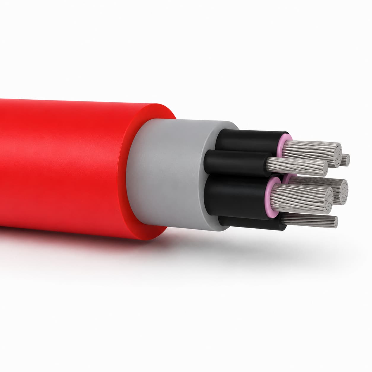
Medium-voltage cable construction should be described layer by layer. Similar-looking cross sections may use different screen areas, earth-conductor layouts, pilot functions or termination methods, and those differences can change both protection-system behavior and accessory selection.
| Component | Primary function | What to confirm |
|---|---|---|
| Power conductor | Carries load current; fine stranding supports flexibility | Material, class/stranding, area, resistance, short-circuit duty and terminal range |
| Conductor and insulation screens | Control the electrical field around the insulation | Material, application method, strippability and termination compatibility |
| Insulation | Provides the main dielectric barrier | Compound, thickness, temperature class, voltage tests and applicable standard |
| Metallic screen or braid | Provides a defined electrical screen and may contribute to fault-current return | Material, area/coverage, fault duty, bonding and termination method |
| Grounding conductor | Provides the equipment-grounding path | Number, size, arrangement, connection and fault duty |
| Ground-check or pilot conductor | Supports the specified monitoring, control or protection circuit | Number, size, voltage/function, insulation, connections and compatible monitor |
| Reinforcement, fillers and outer jacket | Maintain geometry and protect against the stated mechanical/environmental duty | Complete construction, test evidence, dimensions and repair/termination interface |
Do not use grounding conductor, ground-check conductor and metallic screen as interchangeable terms. In the United States, 30 CFR 75.803 is one jurisdiction-specific example of a fail-safe ground-check circuit requirement for defined high-voltage resistance-grounded systems. Other mines and countries use different rules and system designs.
4. Turn movement into reel and route data
A powered reel is a mechanical system, not just cable storage. Record the drum core and flange diameters, usable width, cable entry, number of layers, travel length, speed, acceleration, tension control and direction changes. Add every roller, sheave, fleet angle, S-bend, hanging section and transition point.
For a trailing route, describe ground contact, pulling method, vehicle crossings, cable handlers, route relocation and exposure to irregular impact or crushing. WorkSafe Western Australia distinguishes trailing and reeling cable duties; the TEBAOFLEX reeling cable vs trailing cable guide translates that difference into application questions.
A data sheet may say “flexible”; the drum still responds to diameter, tension, speed and alignment. Ask for the minimum bend radius for both installation and the stated operating duty, because a static bend value should not be treated as a dynamic-reeling approval.
5. Match the jacket and complete construction to the site
List the actual hazards rather than requesting a “heavy-duty” jacket. Include abrasion, cuts, crushing, impact, water or immersion, oils, process chemicals, mud, ozone, sunlight, flame requirements and minimum/maximum temperature. State whether more than one hazard acts at the same location.
Material names such as CPE, PCP, rubber or TPU are useful starting points, but they do not establish service life by themselves. Jacket thickness, reinforcement, cure, compatibility with the underlying cable and the applicable test methods all matter. Request the test standard, condition and result required by the project instead of relying on an unqualified resistance claim.
6. Close the installation, termination and maintenance gaps
Confirm ordered length, drum packing, pulling plan, couplers, glands, stress-control or termination kits, junction boxes, strain relief and cable-entry geometry. A suitable cable can still be damaged by an undersized reel, a sharp guide, poor alignment or a termination that transfers machine pull into the conductors.
Define inspection frequency, route checks, electrical tests, rejection criteria and authorized repair methods in the site maintenance plan. For defined U.S. underground-coal applications, 30 CFR 75.827 addresses guarding of trailing cables, while 30 CFR 75.830 addresses high-voltage trailing-cable splicing and repair. Do not use this article as a repair procedure.
7. Name the standard, edition and acceptance evidence
“To mining standard” is not a complete requirement. State the jurisdiction, mine type, voltage system, equipment approval basis, standard designation and edition. In North America, the ICEA S-75-381 / NEMA WC 58 scope covers portable and power-feeder cables for mines and similar applications. IEC, DIN/VDE, AS/NZS, SANS and other project paths use different designations and acceptance routes.
For U.S. underground coal systems, requirements can also involve high-voltage electrical protection under 30 CFR 75.824 and portable trailing-cable provisions under 30 CFR 18.35. These references are deliberately scoped: they are not universal requirements for every mine or country.
A worked example of acceptance evidence: for a 12/20 kV bucket-wheel excavator reeling cable, a Polish mining company listed the measured values its factory test report had to contain and had its QC inspector witness the tests, as documented on the bucket-wheel excavator reeling cable case page.
Medium-voltage mining cable RFQ checklist
A useful quotation starts with application data, not only a cable name. Attach the single-line diagram, cable schedule, equipment manual excerpt, route sketch, reel drawing and existing cable marking where available.
Name the equipment, installation, mine type, route length and every moving section.
State U0/U, maximum system voltage, frequency, load and starting current, fault duty, earthing and protection clearing time.
List power cores, grounding conductors, screens, pilots or ground-check conductors and their system functions.
Give trailing/reeling duty, drum and sheave dimensions, layers, speed, tension, torsion, S-bends, cycles and handling method.
Record temperature, water, oils, chemicals, UV, abrasion, impact, crushing and flame requirements.
Specify couplers, glands, terminations, length/drum schedule, standard edition, approvals, tests, inspection and deviation documents.
Review the TEBAOFLEX mining and tunneling cable range, then send the completed application data for a technical quotation. Final selection and approval remain project-specific.
Frequently asked questions
What makes a mining cable medium voltage?
The governing electrical system and cable standard define the voltage class. Always use the complete U0/U and maximum-system-voltage designation from the project; do not rely on the term medium voltage alone.
Is a 15 kV utility cable suitable for mining equipment?
Not automatically. A fixed-installation 15 kV cable may meet the electrical voltage requirement but lack the conductor flexibility, grounding or ground-check arrangement, reinforcement, jacket, dynamic bend performance, accessories or approval required for the mining duty.
How do I choose a medium-voltage mining cable size?
Calculate conductor area from load and starting current, route length, installation, ambient conditions, voltage drop, fault duty and protection clearing time. Then confirm that the proposed size and complete construction are available for the required trailing, reeling or feeder duty.
Is every flexible MV mining cable suitable for reeling?
No. Reeling adds repeated bending under tension, drum-layer pressure, speed, acceleration and possible torsion. Provide the reel and route data so the cable manufacturer and responsible engineer can validate the proposed construction.
What determines medium-voltage mining cable price?
A quotation depends on the voltage class, copper area, core, screen, earth and pilot arrangement, jacket and reinforcement, cable dimensions, ordered length, required tests or approvals, accessories, marking and drum packing. Provide the complete application schedule for a comparable price.
Sources and editorial scope
This guide uses current TEBAOFLEX product records for product-specific statements and standards or regulator pages for scope and safety boundaries. It is a selection aid, not an engineering calculation, approval certificate or repair procedure.
Compare current product references
Use these pages after the electrical system and movement duty are defined.