








Case 17 · Vietnam · Portal and gantry cranes · Flat rubber cable
NGFLGOEU-J 0.6/1 kV 3×50+1×16 mm² Flat Festoon Cable for Portal and Gantry Cranes in Vietnam
An industrial-supply distributor in Vietnam won a tender to replace damaged power cable on portal and gantry cranes that work at construction yards and ports in the Ho Chi Minh City area. The tender fixed the cable as NGFLGOEU-J 0.6/1 kV 3×50+1×16 mm², a flat rubber cable 66 mm wide and 22 mm thick. TEBAOFLEX made 235 m in one length, with Class 5 tinned-copper conductors, EPR insulation and a black polychloroprene sheath, measured the finished cable on the drum and packed it for export in November 2026.
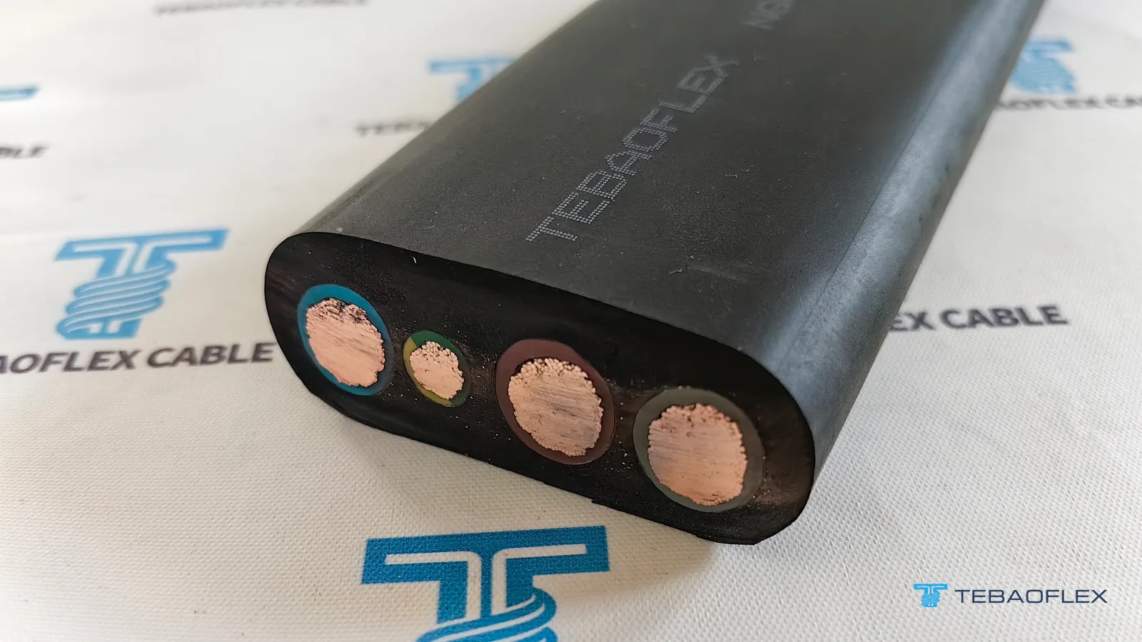
Project at a glance
This project record documents 235 m of NGFLGOEU-J 0.6/1 kV 3×50+1×16 mm² flat rubber festoon cable supplied in one continuous length for portal and gantry cranes in southern Vietnam, built to the tender’s nominal 66 × 22 mm profile and checked with a conductor resistance reading and caliper measurements before the drum was packed.
| Order item | Recorded detail |
|---|---|
| Application | Replacement power cable for portal cranes and gantry cranes at construction yards and ports in the Ho Chi Minh City area |
| Customer | Industrial-supply distributor in Vietnam, supplying the crane operator under a tender (names not published) |
| Cable | NGFLGOEU-J 0.6/1 kV, 3 × 50 mm² power cores + 1 × 16 mm² green-yellow protective core, flat |
| Conductors | Class 5 fine-stranded tinned copper |
| Insulation and sheath | EPR rubber insulation (3GI3); black polychloroprene (PCP) rubber sheath (5GM3) |
| Nominal size | 66 mm wide × 22 mm thick |
| Length | 235 m in one length: 230 m for the cranes and 5 m for the inspection sample needed in Vietnam |
| Site conditions | Hot, humid tropical climate; ambient temperature 30 to 40 °C |
| Dates | Print and length agreed 7 October 2026; production started 9 October; finished cable measured 5 and 10 November |
What is NGFLGOEU-J 0.6/1 kV 3×50+1×16 mm² cable?
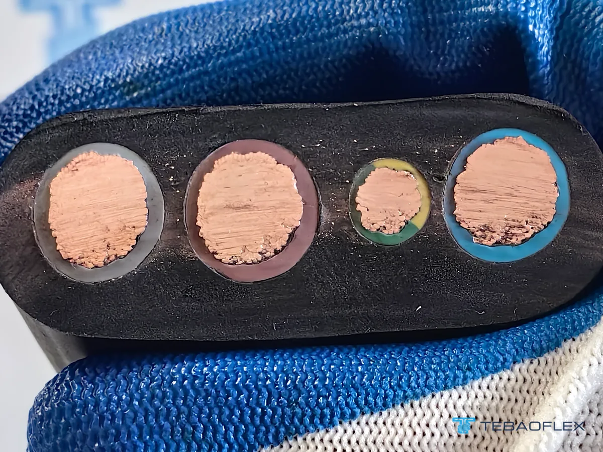
NGFLGOEU-J 3×50+1×16 mm² is a flat rubber cable with three 50 mm² power cores and one 16 mm² green-yellow protective core laid side by side in a single row. NGFLGÖU is the German type name for rubber-insulated, rubber-sheathed flat flexible cables to DIN VDE 0250-809: FL stands for flat, the two Gs for the rubber insulation and the rubber sheath, and ÖU for an oil-resistant, flame-retardant sheath. The -J at the end says that the cable has a green-yellow protective core.
- Class 5 tinned-copper conductor: 50 mm² in the three power cores
- Polyester separator tape over each conductor
- EPR rubber insulation (compound 3GI3), coloured blue, brown and grey on the power cores
- Black polychloroprene (PCP) rubber sheath (compound 5GM3), extruded around all four cores
- Protective core: 16 mm² tinned-copper conductor with green-yellow EPR insulation

| Item | This order |
|---|---|
| Designation on the sheath | NGFLGOEU-J 0.6/1kV 3×50+1x16mm² |
| Rated voltage | 0.6/1 kV, as specified in the tender and on the order datasheet |
| Power cores | 3 × 50 mm², Class 5 tinned copper, EPR insulation 1.6 mm; blue, brown and grey |
| Protective core | 1 × 16 mm², Class 5 tinned copper, EPR insulation 1.2 mm; green-yellow |
| Separator | Polyester tape over each conductor |
| Core arrangement | Four cores parallel in one row, not twisted together |
| Insulation compound | EPR, compound 3GI3 (DIN VDE 0207 Part 20) |
| Sheath | Black polychloroprene (PCP) rubber, compound 5GM3 (DIN VDE 0207 Part 21) |
| Nominal size | 66 mm wide × 22 mm thick |
| Length supplied | 235 m in one length on one drum |
The family data, with the other core counts and sizes, is on our NGFLGOEU flat festoon cable product page. The catalogue rows for four 50 mm² cores are narrower and thinner than the 66 × 22 mm the tender asked for, and they have four equal cores, so this cable was built to the tender's dimensions and core sizes rather than taken from a catalogue row. The tender asked for tinned conductors; on cranes that work outdoors in humid air, the tin layer protects the fine copper wires from corrosion. What tinning changes, and what it does not, is set out in our comparison of tinned and bare copper conductors.
Why is a crane cable flat, and what does anti-torsion mean?
In a flat cable the cores lie side by side, so the cable bends easily across its thin side and every core bends on the same radius. That suits a power cable that hangs in loops under a crane and opens and closes in one plane each time the crane or its trolley travels. The tender called this one a flat-type anti-torsion flexible cable: the parallel cores are not twisted together, and the flat shape keeps the cable from rotating as the loops move.
The other side of this is that a flat cable must not be twisted or bent across its width; our product data states that torsional stress is not allowed. The same data gives a guidance speed of up to 180 m/min for trolley festoon systems and a flexing temperature range of −35 °C to +80 °C, so the 30 to 40 °C ambient at the site is well inside the range. The polychloroprene sheath is the part that faces the weather: the product data lists resistance to oil, ozone, UV, moisture and weathering for outdoor use. How the cable, the trolleys and the track work together is explained in our guide to festoon systems and their cables.
How much current and tension can the 3×50+1×16 mm² flat cable take?
Our NGFLGOEU table lists 212 A for the 50 mm² four-core flat cable, free in air at 30 °C ambient with the conductor at 90 °C, on the basis of DIN VDE 0298-4. At the 40 °C the site can reach, the correction factor for a 90 °C conductor is 0.91, which gives about 193 A. The permitted pull is 15 N/mm² of conductor: with 166 mm² of copper in the four cores, that is 2,490 N.
| Quantity | Value | Basis |
|---|---|---|
| Current, 30 °C ambient | 212 A | NGFLGOEU product table, 50 mm² four-core flat cable, free in air, DIN VDE 0298-4 |
| Current, 40 °C ambient | about 193 A | Calculated: 212 A × 0.91 |
| Maximum conductor temperature | 90 °C | NGFLGOEU product data |
| Permitted tensile load | 2,490 N | Calculated: 15 N/mm² × 166 mm² (3 × 50 + 16) |
| Minimum bending radius | 110 mm at 22 mm thickness | Calculated: 5 × cable thickness, NGFLGOEU product data |
The 40 °C figure, the tensile load and the bending radius are calculations from published values, not tests on this order. The current rating assumes one cable in free air; where several power cables lie against each other on the same carrier, a grouping factor reduces it further. The bending radius of a flat cable is counted on its thickness because that is the plane it bends in: on the 23.3 mm measured on this cable, 5 × thickness is about 117 mm. Both rules are covered in our article on how minimum bending radius is set for round and flat cables, and the way a tension limit is applied to a moving cable is worked through in our selection guide for reeling cables.
What did the conductor resistance check show?
A resistance bridge reading taken during production, on 16 October 2026, measured a 1 m length of the 50 mm² conductor at 0.3862 mΩ at 25 °C, which the instrument corrects to 378.83 mΩ/km at 20 °C, or about 0.379 Ω/km. IEC 60228 allows at most 0.393 Ω/km at 20 °C for a 50 mm² Class 5 conductor of tinned copper, so the reading is about 3.6 % below the limit.
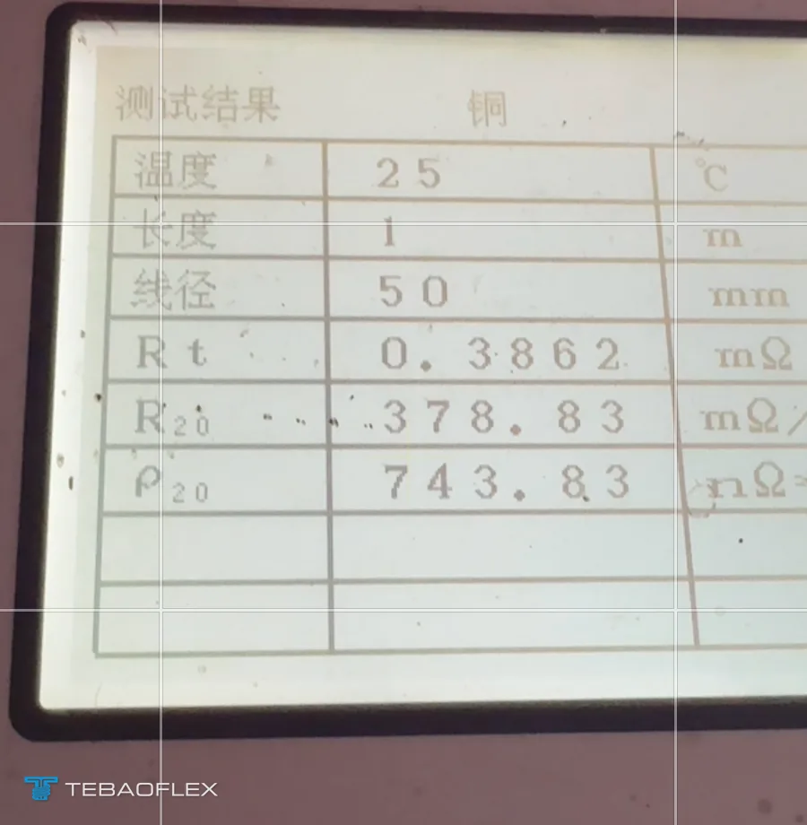
The limit comes from IEC 60228, which sets a maximum DC resistance for each conductor size and class; for tinned wires it is slightly higher than for plain copper, 0.393 against 0.386 Ω/km at 50 mm². This is a single production reading on one power conductor, shown here as it was taken. It is not a full routine test report. What a buyer can ask a factory to measure before shipment, and what each test proves, is covered in our article on what a cable factory acceptance test covers.
Why did the cable stay 66 mm wide?
On 27 October 2026, while the cable was in production, our engineer proposed a thicker sheath that would bring the width up to 70 mm at most, if the cranes' cable carriers had room for it, because in his view a thicker sheath makes a moving cable more robust. The crane operator declined: the 66 mm width was written into the tender documents, and changing a tender specification would have involved several departments and a possible penalty for the distributor. The cable was made to the 66 mm in the contract.
The finished cable was measured with a caliper on the drum on two days. On 5 November it read 65.06 mm across the width and 23.36 mm across the thickness; on 10 November, 65.07 mm and 23.26 mm. Against the nominal 66 × 22 mm, the width is about 0.9 mm under and the thickness about 1.3 mm over.

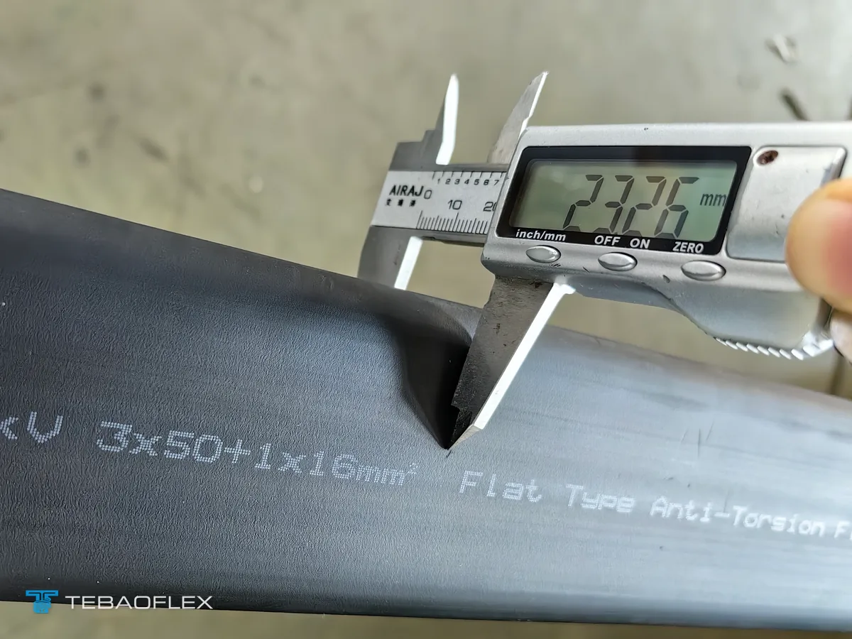
The lesson for anyone writing a tender is to give the cable's dimensions as limits rather than as single figures: the largest width and thickness the carriers and clamps accept, and a tolerance. That leaves the maker room to set the sheath thickness for the duty, and it gives the buyer a clear test for the delivered cable.
What does the print say, and why one 235 m length?
The print was agreed on 7 October 2026, before production. It gives the maker, the type, the rated voltage, the size, the cable description and the standard family, followed by a running metre count, and it repeats once every metre. The distributor's first proposal also listed the conductor class and the dimensions; that text was too long to fit once in each metre with the metre count, so it was shortened.
TEBAOFLEX NGFLGOEU-J 0.6/1kV 3×50+1x16mm² Flat Type Anti-Torsion Flexible Cable DIN VDE Standard 000M … 235M


The cranes needed 230 m, and the distributor added 5 m as an inspection sample for the authorities in Vietnam, choosing to receive all 235 m as one uncut length with the metre count running from 000M to 235M. Ask for such a sample length when the order is placed, so that it is made in the same run as the rest.
From the contract to the packed drum
Production started on 9 October 2026, two days after the print and the length were settled, and the finished cable was measured on the drum on 5 November. The distributor asked to inspect the finished cable in our warehouse over a video call before shipment, a check its company makes on its suppliers, and we arranged it. The drum was then closed with wooden lagging, strapped to a pallet and shipped with a certificate of origin.
| Date (2026) | Step |
|---|---|
| 7 October | Print, 235 m single length and drum marking agreed |
| 9 October | Production started |
| 16 October | Conductor resistance reading on the 50 mm² conductor |
| 27 October | Width question settled: 66 mm as in the tender |
| 5 November | Finished cable measured on the drum |
| 10 November | Second measurement; cut samples photographed |
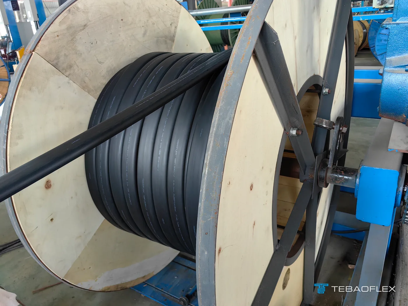

The drum is 1.4 m across the flanges and 0.97 m wide, and carries a TEBAOFLEX label with the cable size and the 235 m length. A different crane supply for a site in the same country, a round reeling cable for a ship unloader, is documented in our ship unloader reeling cable project in Vietnam.
For a broader crane subsystem matrix comparing 1+1+1+1 flat festoon saddle fit, narrow radial monospiral reels and round aramid-braided torsional drums, read our flat cable vs round cable guide for crane festoons and reels.
What to send for a flat crane cable quote
Sending your core sizes, rated voltage, maximum carrier clamp width and thickness with tolerances, trolley travel speed, ambient temperature, and required single-piece plus inspection-sample lengths allows our engineering team to confirm the flat cable profile before production.
- Number of cores and cross-sections, including a reduced protective core if required, for example 3 × 50 + 1 × 16 mm²
- Rated voltage and the standard or type named in your specification
- The largest width and thickness the cable carriers and clamps accept, with a tolerance
- How the cable is carried: festoon trolleys or another arrangement, loop depth, travel length and speed
- Ambient temperature range, outdoor exposure and contact with oil
- Tinned or plain copper conductors
- Print text, length per drum, and any sample length needed for import inspection
- Documents required with the delivery, such as a certificate of origin
Subsystem layouts across trolley festoons, spreader reels and gantry drums are mapped on our port and container crane cable solutions page, and the full round and flat catalogue is in our port and festoon cable range. The written quotation confirms the construction, the dimensions and the delivery time for your order.
Send your core sizes and carrier dimensions for a quote →
Questions on NGFLGOEU-J flat crane cable
What is NGFLGOEU-J 3×50+1×16 cable?
NGFLGOEU-J 3×50+1×16 is a flat rubber-insulated, rubber-sheathed flexible cable with three 50 mm² power cores and one 16 mm² green-yellow protective core laid side by side. NGFLGÖU is the German type for flat rubber cables to DIN VDE 0250-809, used mainly on crane festoon systems; the -J marks the green-yellow core. The cable in this case was specified as 0.6/1 kV, with Class 5 tinned-copper conductors, EPR insulation and a black polychloroprene sheath, nominally 66 mm wide and 22 mm thick.
Why are festoon cables flat?
A flat festoon cable has its cores side by side in one row, so it bends easily across its thin side and every core bends on the same radius. That suits a cable that hangs in loops from trolleys and opens and closes in one plane each time the crane travels. The flat shape also keeps the cable from rotating in the loop. A flat cable must not be twisted or bent across its width.
How much current can NGFLGOEU 3×50+1×16 mm² carry?
The TEBAOFLEX NGFLGOEU table lists 212 A for the 50 mm² four-core flat cable, with the cable free in air at 30 °C ambient and the conductor at 90 °C, on the basis of DIN VDE 0298-4. At 40 °C ambient the correction factor for a 90 °C conductor is 0.91, which gives about 193 A. Cables bunched together on one carrier need a further reduction.
What is the minimum bending radius of a flat festoon cable?
The minimum bending radius of a flat cable is taken on its thickness, not its width, because the cable bends across its thin side. For NGFLGOEU rubber flat cable it is 5 × the cable thickness: 110 mm for a 22 mm thick cable, and about 117 mm for the 23.3 mm measured on the cable in this case.
What should a tender for flat crane cable specify?
A tender for flat crane cable should give the number of cores and their cross-sections, the rated voltage, and the largest width and thickness the cable carriers and clamps accept, each with a tolerance. It should also state the conductor material, the sheath compound and the length of each piece. Fixing a single width and thickness without a tolerance leaves no room to adjust the sheath later, as this order showed.