









DIN VDE 0250-813, JCS & IEC 60794 reeling engineering guide
Specifying a fiber-optic composite reeling cable requires matching five interdependent constraints before production: round torsional vs flat monospiral drum profile, split-earth geometry (such as 3×35/3E vs 2×25/2) to free interstice space for the optical subunit, single-mode 9/125 µm vs multimode 50/125 or 62.5/125 µm rotary-joint optics, drum groove minimum/maximum outside diameter and linear mass ceilings, and pre-measured breakout tail lengths at both ends. Selecting by voltage and phase cross-section alone routinely causes drum-groove wedging, fiber micro-bending attenuation or short slip-ring leads during commissioning.
What separates a fiber-optic composite reeling cable from a fixed hybrid power-optical cable?
A dynamic fiber optic reeling cable (also designated an electro-optical or fiber-optic composite reeling cable) engineered with reference to DIN VDE 0250-813 and IEC 60794-1-2 isolates glass optical fibers from tensile copper elongation up to 15–20 N/mm², multi-layer drum radial crush up to 4.9 kN/m, and repeated bending down to 12 × cable diameter on drums (15 × D over deflection sheaves). Static tray or duct hybrid cables lack excess-fiber-length decoupling and anti-torsion braids, suffering rapid optical attenuation under motorized reel acceleration.
On automated ship-to-shore (STS) quay cranes, rail-mounted gantry (RMG) cranes, ship unloaders and bucket-wheel reclaimers, medium-voltage drive power (3.3 kV to 20 kV) and real-time PLC, safety-interlock and anti-sway camera telemetry travel along the exact same moving gantry span. Combining power, optional 2.5 mm² control bundles and 6 to 24 optical fibers inside one elastomer reeling sheath eliminates a second parallel festoon or data reel, provided three mechanical decouplings are built into the cable:
- Excess fiber length inside crush-resistant buffer tubes: Optical fibers are housed inside fluoropolymer ETFE (7YI1 per DIN VDE 0207) or elastomeric loose buffer tubes with controlled excess fiber length so the glass experiences near-zero tensile strain when tinned-copper phase conductors stretch elastically under dynamic pull.
- Short-pitch helical core lay around a central cradle: In round builds, phase cores, split earth cores and the optical subunit twist at a matched pitch angle around a profiled elastomer or aramid-reinforced center so bending tension alternates into compression across every half-lay rather than kinking the optical tube.
- Embedded anti-torsion double sheathing: An open-weave synthetic or aramid (Kevlar) reinforcing mesh vulcanized between the inner 5GM3 rubber bedding and outer 5GM5 polychloroprene sheath counteracts rotational torque caused by roller deflection and monospiral fleet angles.

How do +FO, -LWL, FG-H-3PNCT and FC-PNCT reeling designations map across DIN VDE and JIS standards?
European crane drawings designate medium-voltage electro-optical reeling cables under DIN VDE 0250-813 as round (N)TSCGEWÖU+FO (or -LWL) for multi-plane torsional drums and flat (N)TSFLCGEWÖU-FO for zero-torsion monospiral slots across 3.6/6 kV to 12/20 kV. Japanese- and Korean-built cranes specify JCS-pattern FC-PNCT (600 V to 6.6 kV) or flat FG-H-3PNCT and FG-3PNCT (3.3 kV and 6.6 kV) tested at 9,000 V or 17,000 V AC for 10 minutes.
| Designation family | Profile & torsion limit | Rated voltage tiers | Typical fiber & control layout | Choose this when |
|---|---|---|---|---|
| (N)TSCGEWÖU+FO / NTSCGEWOU-LWL | Round · up to ±25°/m torsion | 3.6/6, 6/10, 8.7/15, 12/20 kV (DIN VDE 0250-813) | 6–24FO (SM 9/125 or GI 50/125 & 62.5/125) ± 12–24 × 2.5 mm² control | Cylindrical level-wind or monospiral reels with multi-plane sheaves, turnover pits or S-bends |
| (N)TSFLCGEWÖU-FO / -LWL | Flat · 0°/m axial torsion | 3.6/6, 6/10, 8.7/15, 12/20 kV (DIN VDE 0250-813) | 6–24FO in ETFE buffer tube ± 6–12 × 2.5 mm² slot-matched control bundle | Narrow single-slot radial monospiral drums or heavy crane festoons bending in one vertical plane |
| FG-H-3PNCT & FG-3PNCT | Flat · 0°/m axial torsion | AC 3.3 kV & 6.6 kV (JCS 10-min 9 kV / 17 kV AC test) | 6–12 GI 50/125 or 62.5/125 fibers + insulated PE (± 8–12 × 2.5 mm² in FG-H-3PNCT-C) | Japanese-built STS and RMG monospiral crane drums requiring 4.9 kN/m lateral crush strength |
| FC-PNCT-R / FC-PNCT-RF / FC-3PNCT | Round (-R) or Flat (-RF) | 600 V, 0.6/1 kV, 3.3 kV & 6.6 kV (JIS C 3327 / JCS 4364) | 4–24FO (GI 50/125, GI 62.5/125 or SM 9/125) + JIS mm² power/earth cores | Automated RTG, RMG and bulk reclaimers built to Japanese cabtyre cross-sections (14–150 mm²) |
| All-dielectric crane flexible FO | Round non-metallic · festoon / chain | Data-only (0 V power) | 4–24FO tight-buffered or loose-tube inside PUR or 5GM5 rubber sheath | Power cable already exists on a separate drum or busbar and only optical telemetry moves |
Each series maps directly to a dedicated specification schedule: review our (N)TSCGEWÖU and NTSCGEWOU+FO round crane reeling cable page for torsional DIN VDE drums, our (N)TSFLCGEWÖU-FO flat medium-voltage optical reeling schedule for European monospiral reels, our FC-PNCT round and flat composite fibre-optic reeling range for 600 V–6.6 kV Japanese cranes, and our 3.3–6.6 kV FG-H-3PNCT and F-3PNCT crane reeling catalogue. Where power runs separately on conductor rails or a dedicated power drum—such as our Hai Phong Port 6.6 kV F-3PNCT crane reel replacement—specify a standalone all-dielectric flexible crane fibre-optic cable instead of over-building a hybrid cable.
What do split-earth notations like 3×35/3E, 2×25/2 and 4×25/4E actually mean in a composite cable?
In DIN VDE 0250-813 medium-voltage reeling designations (DIN VDE 0250-813), the number before the slash is the combined protective-earth copper cross-section in mm² and the divisor after the slash is the number of sub-conductors sharing it. Thus 2×25/2 means two 12.5 mm² earth cores totaling 25 mm², leaving the third outer interstice open for the optical-fiber subunit without increasing overall cable diameter.
Misreading split-earth notation is one of the most frequent causes of oversized replacement cables on port cranes. If an engineer misinterprets 2×25/2 as two full 25 mm² earth conductors (50 mm² total copper) or forces a single 25 mm² fourth core alongside three phase cores and a 24FO tube, the core pitch circle balloons by 4 to 6 mm—pushing the finished cable outside its monospiral drum groove.
| Earth notation | Physical core / screen arrangement | Per-element vs total Cu area | 20 °C combined PE DC resistance | Confirm before ordering |
|---|---|---|---|---|
| 3×50 + 2×25/2 + 12FO | Two insulated/semiconductive earth cores in 2 outer interstices; 12FO subunit in the 3rd interstice | 2 × 12.5 mm² = 25 mm² total PE | ≤ 0.795 Ω/km (25 mm² IEC 60228 Class 5 tinned basis) | Confirm slip-ring collector has 2 earth termination lugs bonded to the PE ring |
| 3×35 + 3×35/3E + 2×(6×2.5)C + 12FO | Three concentric tinned-copper earth screens helically applied over the 3 phase cores; 2 control bundles + 1 FO in interstices | 3 × 11.7 mm² = 35 mm² total PE/screen | ≤ 0.565 Ω/km (35 mm² combined Class 5 tinned basis) | Ideal when both control cores and FO must share one round sheath without OD growth |
| 3×35 + 4×25/4E + 12FO (flat) | Concentric split earth distributed across parallel flat cores alongside the ETFE-buffered 12FO subunit | 4 × 6.25 mm² = 25 mm² total PE | ≤ 0.795 Ω/km combined | Saves 8–10 mm of flat cable width inside narrow radial monospiral drum slots |
| 3×60 + 1×30 + 12FO (JIS / JCS) | Dedicated single 30 mm² insulated earth core laid up with phase cores and optical unit | 1 × 30 mm² = 30 mm² single PE | JIS C 3102 / JCS 30 mm² schedule | Required when Japanese switchgear expects one discrete green/earth conductor lug |

Should crane reels specify single-mode 9/125 µm or multimode 50/125 and 62.5/125 µm optical fibers?
Under IEC 60794 optical cable standards, single-mode 9/125 µm fibers (ITU-T G.652.D or bend-insensitive G.657.A2) hold cabled attenuation to ≤ 0.40 dB/km at 1310 nm and ≤ 0.30 dB/km at 1550 nm for high-bandwidth Gigabit crane automation, whereas graded-index multimode GI 50/125 µm and GI 62.5/125 µm fibers (≤ 2.8–4.0 dB/km at 850 nm) match legacy crane transceivers and multi-channel fiber-optic rotary joints (FORJ).
Never guess fiber geometry from fiber count—and beware of hybrid tender translations that accidentally write contradictions such as “24FO (62.5/125) single-mode.” Physically, 9/125 µm is a single-mode core/cladding geometry, whereas 50/125 µm (OM2/OM3) and 62.5/125 µm (OM1) are graded-index multimode geometries. Plugging a 9/125 µm single-mode reel cable into a 62.5/125 µm multimode rotary joint causes severe core-mismatch coupling loss across every crane rotation.
| Optical fiber geometry | Standard & mode class | Test wavelength | Max. cabled attenuation | Confirm before ordering |
|---|---|---|---|---|
| SM 9/125 µm (G.657.A1 / A2) | ITU-T G.657.A2 bend-insensitive single-mode | 1310 nm / 1550 nm | ≤ 0.40 dB/km (1310 nm) · ≤ 0.30 dB/km (1550 nm) | Preferred for new automated STS/RMG cranes, Tight drum radii and 10G Ethernet backbones; confirm single-mode FORJ |
| SM 9/125 µm (G.652.D) | ITU-T G.652.D standard single-mode | 1310 nm / 1550 nm | ≤ 0.40 dB/km (1310 nm) · ≤ 0.30 dB/km (1550 nm) | Standard on 8.7/15 kV 24FO ship-unloader and long-travel quay reels; verify minimum splice-cassette coiling radius |
| GI 50/125 µm (OM2 / OM3) | IEC 60794 / ITU-T G.651.1 graded-index multimode | 850 nm / 1300 nm | ≤ 2.8–3.0 dB/km (850 nm) · ≤ 1.0 dB/km (1300 nm) (≤ 4.0 dB/km JCS basis) | Most common on Japanese FG-H-3PNCT / FC-PNCT cranes and multi-channel optical slip rings |
| GI 62.5/125 µm (OM1) | IEC 60794 graded-index multimode | 850 nm / 1300 nm | ≤ 3.0–3.3 dB/km (850 nm) · ≤ 1.0 dB/km (1300 nm) (≤ 4.0 dB/km JCS basis) | Specify only when replacing an existing 62.5/125 µm crane bus, PROFIBUS optical link or legacy FORJ |
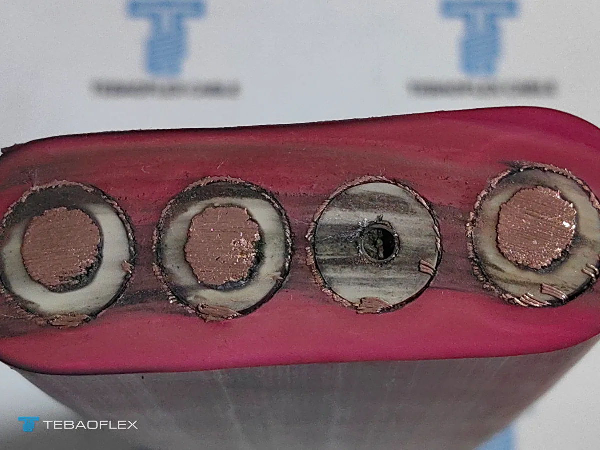
For a production harbor-crane replacement showing how 2×25/2 split earth packed three 6/10 kV phases, 16 screened control cores and 24 multimode 62.5/125 µm fibers at 51.69–52.54 mm inside a strict 48–53 mm groove limit across 125 m and 175 m uncut drums, see our Vladivostok Port 6/10 kV (N)TSCGEWÖU+FO 24FO crane reeling cable case.
How do monospiral drum OD windows, linear mass limits and pulling tension constrain composite builds?
Existing crane reels constrain replacement composite cables through a four-part mechanical envelope: minimum and maximum outside diameter (for example 48.0 to 53.0 mm) to match machined drum grooves, maximum linear mass (kg/m) within drive motor torque, dynamic acceleration tension (checked against 15–20 N/mm² of phase copper per DIN VDE 0298-3), and travel speed up to 180–200 m/min.
A recent port-crane replacement engineering review for a 6/10 kV 3×35 + 2×25/2 + (16×2.5)C + 24FO reeling cable illustrates why all four numbers must be solved simultaneously rather than picked from separate catalogue pages:
- Tight 48–53 mm outside-diameter window: Packing three screened 6/10 kV 35 mm² cores, sixteen 2.5 mm² EPR control cores and a 24-fiber optical subunit easily exceeds 56 mm if laid up with thick fillers. Splitting the earth into two 12.5 mm² interstitial cores (2×25/2, ≤ 0.795 Ω/km at 20 °C per IEC 60228) and grouping the control cores compactly keeps the finished diameter inside the 48 to 53 mm drum groove window.
- Linear mass ceiling (≤ 4.35 kg/m): Spring-assisted and torque-motor reels are counter-balanced for a maximum suspended cable mass; exceeding 4.35 kg/m on a 125 m or 175 m span overloads the reel gearbox during high-speed retrieval at 200 m/min.
- Dynamic pulling load (≥ 3,150 N) vs copper cross-section: Three 35 mm² phase conductors total 105 mm² of copper. Under standard TS reeling rules (15 N/mm²), copper alone carries 1,575 N; even under TTS rules (20 N/mm²), copper carries 2,100 N. Meeting a 3,150 N dynamic acceleration pull without transferring strain into the 24 optical fibers requires pairing a central aramid strength member with an outer aramid anti-torsion braid between the 5GM3 inner and 5GM5 outer sheaths.
| Composite configuration | Voltage & profile | Finished OD or H × W (mm) | Approx. mass (kg/km) | Tensile / speed basis | Confirm before ordering |
|---|---|---|---|---|---|
| 6/10 kV 3×35 + 2×25/2 + (16×2.5)C + 24FO | 6/10 kV Round (N)TSCGEWÖU+FO | 48.0–53.0 mm (groove-controlled) | ≤ 4,350 (≤ 4.35 kg/m) | ≥ 3,150 N w/ central + braided aramid; up to 200 m/min | Verify exact min/max drum groove pitch and slip-ring housing bore |
| 8.7/15 kV 3×35 + 3×35/3 + (20×2.5)C + 24FO (9/125) | 8.7/15 kV Round MV 24FO | 56.3–58.7 mm | 5,110 | 12 × D drum / 15 × D sheave; 172 A ref. | Proven on ship-unloader reels requiring 20 control cores + 24 SM fibers |
| 6/10 kV 3×50 + 4×25/4E + 6/12FO | 6/10 kV Flat (N)TSFLCGEWÖU-FO | 29.3 × 96.5 mm (max 31.0 × 99.1) | 4,810 | 2,250 N at 15 N/mm² Cu; 465 mm min bend | Check monospiral inside flange width exceeds 99.1 mm plus clearance |
| 8.7/15 kV 3×120 + 1×70 + 12×2.5 + 12FO | 8.7/15 kV Flat TF-FLC Hybrid | 34.5 × 120.0 mm (max 38.4 × 123.8) | 9,750 | Up to 7.9 kN reinforced / 2.6 kN working; 500 mm bend | Slot-matched flat replacement for high-capacity STS quay cranes |
| 6.6 kV FG-H-3PNCT-C 3×60 + 1×30 + 12×2.5 + 12FO | 6.6 kV Flat JCS Hybrid | 38.5 × 118.0 mm | 7,850 | 17,000 V / 10 min AC test; ≤ 4.9 kN/m crush | Japanese 6.6 kV STS/RMG monospiral crane replacement |
Full specifications for the 8.7/15 kV 24-fiber ship-unloader build are published on our 8.7/15 kV medium-voltage reeling cable with integrated 24FO page and documented in field service in our Duyen Hai 2 ship unloader 8.7/15 kV 24FO reeling cable case study. Step-by-step formulas for drum barrel diameter, spring/motor torque and multi-layer ampacity derating are covered in our reeling cable drum sizing and tension calculation guide.
Why must 2,000 mm staggered breakout tails and cold-shrink terminations be specified before production?
Composite reeling cables require 1,500 to 2,000 mm of stripped core length at both the reel slip-ring hub and the quay turnover pit so medium-voltage cold-shrink stress cones, 2.5 mm² control terminal blocks and fusion-spliced 12FO/24FO optical rotary-joint pigtails can route without tight bends. Omitting tail allowance from drum cut lengths (such as 125 m or 175 m) leaves the active reeling span short.
Three practical termination and commissioning checks prevent damage to the optical core during installation:
- Do not size medium-voltage connectors by outer sheath diameter alone: Buyers frequently ask for a simple clamp connector matched only to the 50 mm outer jacket. Medium-voltage reeling terminations (such as outdoor cold-shrink kits for 6/10 kV or 8.7/15 kV) must match the individual conductor cross-section, diameter over the 3GI3 EPR insulation, and semiconductive screen stripback dimensions, while an anchored strain-relief stocking grips the outer 5GM5 rubber sheath ahead of the breakout crotch.
- Specify factory-installed vs site-terminated optical fan-outs upfront: TEBAOFLEX can supply uncut drum lengths with sealed ends for local cold-shrink and LC/SC/ST fusion splicing on site, or fit factory pre-terminated 2,000 mm staggered power, control and armored optical fan-out tails when connector pinouts and gland threads are confirmed on the order drawing.
- Verify optical continuity with bi-directional OTDR before and after drum mounting: Routine factory verification combines 5-minute or 10-minute MV AC dielectric testing (per our medium-voltage cable factory acceptance testing guide) with optical attenuation measurement at 850/1300 nm (GI) or 1310/1550 nm (SM). During crane stringing, eliminate axial twist and keep fleet angles within ±1.5°—because reeling corkscrew deformation (analyzed in our reeling cable corkscrew failure and anti-torsion guide) pinches internal optical tubes long before copper phase cores open.
For low-voltage 0.6/1 kV crane spreaders, jibs and festoon runs under roughly 150 to 250 m where integrated copper fieldbus pairs replace active optical media converters, review our hybrid power and CAN-BUS / PROFIBUS L2 crane reeling cable guide.
Pre-RFQ specification checklist for electro-optical crane and mining reeling cables
Sending a complete mechanical, electrical and optical envelope at inquiry stage lets TEBAOFLEX engineers model core lay-up diameter, copper-plus-aramid tensile capacity and optical buffer protection on an approval drawing before extrusion begins.
- Target designation & drum profile: Round (N)TSCGEWÖU+FO / FC-PNCT-R for multi-plane or cylindrical level-wind drums, or flat (N)TSFLCGEWÖU-FO / FG-H-3PNCT / FC-PNCT-RF for narrow zero-torsion monospiral slots.
- System voltage & test basis: Nominal U0/U (0.6/1, 3.3, 3.6/6, 6.6, 6/10, 8.7/15 or 12/20 kV) and routine AC test requirement (such as 17 kV / 5 min DIN VDE 0250-813 or 17 kV / 10 min JCS).
- Power, split-earth & control cores: Phase count × mm², split-earth geometry (e.g. 3×35/3E vs 2×25/2 vs discrete PE core), and screened or unscreened 1.5 / 2.5 mm² control core count.
- Optical fiber count, mode & tails: Exact fiber count (6, 12, 18, 24 or 36 FO), mode geometry (SM 9/125 µm G.657.A2/G.652.D, GI 50/125 µm or GI 62.5/125 µm), and whether 2,000 mm breakout tails or pre-terminated connectors are needed.
- Drum groove & dynamic duty limits: Minimum and maximum permissible cable OD (or flat H × W), linear mass limit (kg/m), drum barrel diameter, deflection sheave diameters, travel speed (m/min), dynamic pulling force (N), ambient temperature range (such as −30 °C to +80 °C) and exact uncut length per drum (e.g. 125 m + 175 m).
As of November 2026, TEBAOFLEX manufactures custom round and flat electro-optical reeling cables at our Taicang factory from a 50 m minimum order quantity (MOQ), with a standard production lead time of 7 to 45 working days depending on custom lay-up tooling, optical core configuration and order schedule. Compare subsystem architectures on our reeling cable solutions hub, browse the complete port and festoon cables catalogue, or submit your drum groove window and +FO cable specification for engineering review.
Frequently asked questions
What does +FO or -LWL mean in (N)TSCGEWÖU+FO and (N)TSFLCGEWÖU-LWL designations?
In DIN VDE 0250-813 medium-voltage reeling nomenclature, +FO (English: fiber optics) and -LWL (German: Lichtwellenleiter) both indicate an integrated optical-fiber subunit laid up inside the power cable core alongside the screened phase, earth and optional control conductors. Neither suffix specifies fiber count or mode by itself, so purchase drawings must state the exact count and core/cladding geometry—such as 12FO GI 50/125 µm, 12FO GI 62.5/125 µm or 24FO SM 9/125 µm.
What is the difference between 3×35/3E and 2×25/2 split-earth notation on reeling cables?
Under DIN VDE 0250-813 notation, the divisor after the slash states how many symmetrical earth elements share the total protective-earth cross-section. A 3×35 + 3×35/3E construction divides 35 mm² of earth copper across three interstices or concentric phase screens (about 11.7 mm² each), whereas 3×35 + 2×25/2 places two 12.5 mm² earth conductors (25 mm² combined, ≤ 0.795 Ω/km at 20 °C per IEC 60228) in two outer interstices so the third interstice can house a 12FO or 24FO optical subunit without enlarging cable diameter.
Should automated port cranes specify single-mode 9/125 µm or multimode 50/125 and 62.5/125 µm fibers?
Specify single-mode 9/125 µm (ITU-T G.652.D or bend-insensitive G.657.A2, ≤ 0.40 dB/km at 1310 nm and ≤ 0.30 dB/km at 1550 nm) for long ship-to-shore quay travel, high-channel-count crane automation and modern single-mode fiber-optic rotary joints (FORJ). Specify graded-index multimode GI 50/125 µm (≤ 2.8–3.0 dB/km at 850 nm) or GI 62.5/125 µm (≤ 3.0–3.3 dB/km at 850 nm) when connecting into existing multimode crane PLCs or multi-pass FORJs that require a larger core alignment aperture.
Why do crane drum replacement specifications state both a minimum and maximum cable outside diameter?
Cylindrical level-wind grooves and narrow monospiral drum slots have fixed machined geometry: if a composite reeling cable exceeds the upper OD limit (for example > 53 mm), adjacent wraps rub flanges or climb out of pitch; if it falls below the lower OD limit (for example < 48 mm), gaps open between turns so upper layers wedge downward under tension and crush the optical subunit. State both minimum and maximum permissible OD plus linear mass (kg/m) on replacement RFQs.
When must a flat electro-optical cable like (N)TSFLCGEWÖU-FO or FG-H-3PNCT be chosen over round (N)TSCGEWÖU+FO?
Select flat (N)TSFLCGEWÖU-FO (3.6/6 to 12/20 kV) or Japanese-pattern FG-H-3PNCT / FC-PNCT-RF (600 V to 6.6 kV) when a narrow radial monospiral drum stacks turns in a single vertical plane with 0°/m axial torsion. Whenever the cable route passes over multi-plane deflection sheaves, horizontal-to-vertical turnover guides or cylindrical level-wind drums experiencing up to ±25°/m torsion, select round aramid-braided (N)TSCGEWÖU+FO or FC-PNCT-R.
Why should 2,000 mm staggered breakout tails be specified on composite reeling cables?
Inside a crane reel hub and at the quay turnover pit, medium-voltage phase cores route to high-voltage slip rings or stress-cone terminations while 2.5 mm² control cores land on terminal blocks and the 12FO/24FO optical tube routes into a separate splice cassette for the fiber-optic rotary joint (FORJ). Specifying 2,000 mm factory breakout tails (or adding 4 to 5 m of allowance to total drum length) prevents installers from coming up short on the active reeling span.