









Reeling cable mechanics
A reeling cable corkscrews (pigtails or Z-kinks) and birdcages when axial torsion and tensile elongation force the internal copper cores out of sync with the outer sheath. The four direct triggers are unspooling over a stationary drum flange during installation, level-wind fleet angles exceeding 1.5° to 2° (or guide angles above 5° under IEC 60204-1), reverse S-bends spaced closer than 20 × cable diameter, and pulling tension exceeding 15 to 20 N/mm² on a cable without an embedded anti-torsion braid. Once corkscrewed, copper deformation is permanent: retire or cut back the twisted length and correct the reel geometry before spooling a replacement.
Corkscrewing, birdcaging and jacket creep: what each deformation tells you
Maintenance crews on underground LHD loaders, tunnel-boring machines (TBMs), drill masts, and stockyard reclaimers often group every spiral cable distortion under the single word “corkscrewing.” Separating the exact external shape tells you whether twist entered on installation day, built up over thousands of misaligned guide cycles, or came from hydraulic reel over-tension.
| Deformation pattern | What it looks like on the floor or drum | Primary mechanical mechanism | Where it typically concentrates |
|---|---|---|---|
| Helical corkscrewing (pigtailing) | Whole cable forms a 3-D corkscrew wave or snaps into figure-eight loops whenever tension drops | Locked-in axial torsion from over-flange installation payout or sideways rolling at misaligned guide rollers | Just ahead of the guide funnel, turnaround anchor, or machine cable guide where walking twist hits a fixed clamp |
| Localized birdcaging / core bulge | Outer sheath balloons outward over a 150 to 400 mm span; individual phase cores push ridges through the rubber | Differential core-length migration across tight reverse S-bends or unreinforced single-sheath jacket creep | Immediately before a fixed cable grip, slip-ring entry gland, or rigid turnover sheave |
| Sharp Z-kink after slack throw | Tight angular bend or flattened buckle with snapped pilot or earth strands inside | Reel under-tension or sudden machine reversal throwing slack loops off the drum, followed by high-speed snatch | Near the centre-feed turnaround point or within the first 5 to 15 m off a mobile loader reel |
| Uniform wave after a heavy pull | Outside diameter necks slightly under load, then ripples along the length when relaxed | Tensile overload above 15 to 20 N/mm² plastically stretching copper while the cross-linked elastomer rebounds | High-tension bottom barrel wraps on monospiral reels or long towed trailing runs |
Why stranded copper and rubber sheaths untwist under axial pull
Every multi-core flexible mining and crane cable is built as a helix: fine Class 5 or Class 6 copper wires are bunched or rope-stranded, and the insulated phase, earth, and pilot cores are cabled together at a defined lay pitch around a central filler or cradle. Because of that helical geometry, pulling a cable straight in tension creates an internal untwisting torque—just as pulling a laid fibre rope tries to spin its free end.
In a free-hanging festoon loop, tensile force is negligible and zero torque develops. On a motorized or hydraulic reel, two things happen simultaneously on every travel cycle:
- Sheave milking and jacket creep: As the tensioned cable bends over a guide roller or fairlead sheave, the outer arc of the cable stretches while the inner arc compresses. If the outer sheath is extruded as a single unreinforced tube without an anti-torsion braid locked to an inner sheath, roller contact slowly “milks” the rubber jacket longitudinally toward the fixed end while rotating it relative to the core bundle.
- Plastic copper stretch versus elastic rubber recovery: Copper yields permanently at a small fraction of the strain that cross-linked EPR and polychloroprene (PCP) or polyurethane (TPU) tolerate elastically. When a snatch load stretches the copper conductors by even 0.5 % to 1 %, the rubber jacket contracts back to its original length as soon as tension eases—forcing the now-longer copper cores to buckle sideways into a helical corkscrew or birdcage inside the sheath. Smaller pilot and ground-check conductors often snap during that rebound, triggering the relay faults diagnosed in our mining trailing cable ground-check trip troubleshooting guide.
Fleet angle, reverse S-bends, dead wraps and the 15 N/mm² pull ceiling
Even a premium anti-torsion reeling cable will corkscrew if the reel drive or roller path violates four published mechanical boundaries from IEC 60204-1, DIN VDE 0298-3, and Port Equipment Manufacturers Association (PEMA) reeling practice:
| Mechanical parameter | Engineering limit and standard source | What happens when violated |
|---|---|---|
| Level-wind fleet angle | ≤ 1.5° to 2.0° between guide sheave and cylindrical drum flange | Cable climbs adjacent turns, drops into gaps, and rolls slightly on its axis on every traverse stroke, pumping cumulative twist toward the anchor |
| Guide funnel / drum lateral angle | ≤ 5° in any plane (IEC 60204-1 clause 13.4.3) | Sidewall scrubbing against roller cheeks twists the outer jacket once per revolution |
| Straight recovery between bends | ≥ 20 × overall cable diameter D between two bends; ≥ 20 × D radius for S-type reverse bends on MV reels | Opposing bends without a straight recovery zone prevent opposite-side cores from equalizing path length, causing localized birdcaging |
| Dynamic tensile stress on copper | ≤ 15 N/mm² of phase copper (IEC 60204-1 / DIN VDE 0298-3); up to 20 N/mm² in Australian trailing cable practice | Permanent copper elongation; barrel torque spike on nearly empty monospiral reels (worked out in our reeling cable selection guide) |
| Minimum dead wraps on barrel | ≥ 2 full turns remaining on the reel drum at maximum travel, plus ≥ 2 turns on any fixed-end relief drum | Pulling against the last half-turn yanks directly on the gland clamp, kinking cores at the slip-ring entry |
| Minimum drum and sheave barrel | Low voltage: ≥ 10 × D to 16 × D barrel diameter (5 to 8 × D radius); Over 1 kV: ≥ 24 × D barrel (12 × D radius, PEMA) | Excessive outer-core bending strain and accelerated copper work-hardening |
Check hydraulic and constant-torque electric reels at minimum wound radius (maximum machine payout), not at full reel. Because Tension = Torque ÷ Radius, a monospiral reel whose full-to-empty diameter ratio is 3:1 triples cable tension on the bottom barrel wraps unless the drive regulates torque dynamically.
Why unspooling over a flange ruins a new reeling cable before shift one
Roughly half of early corkscrew complaints occur within the first week after a cable changeout—not because of the machine, but because of how the new cable left the shipping wooden drum.
- Never pull cable off over the side flange of a stationary drum or flat floor coil: Lifting one loop axially over a stationary 1.2 m drum flange injects exactly one 360° twist every 3.8 m. Over a 150 m LHD loader or drill cable, that traps nearly 40 full rotations inside the cable before the end is even terminated.
- Mount the shipping drum on axle jacks in the same plane and rotation sense: Support the delivery drum on a horizontal spindle with manual braking so it pays out from the top (or bottom) straight onto the top (or bottom) of the machine reel without forming an S-bend between the two drums. Before spooling, complete your pre-installation checks using our mining cable arrival inspection and Megger testing guide.
- Release manufacturing and handling torsion before clamping the dead end: Lay out or hang the final end freely before tightening the Kellems mesh grip (spread over 20 to 25 × D) or strain-relief drum so zero residual twist is locked behind the gland.
- Run the 5-cycle chalk-line commissioning test: Chalk a straight line along 20 m of jacket—or record the initial pitch of the factory inkjet print—and cycle the machine slowly five to ten times. A mild, unchanging factory print helix is normal; a line that winds tighter with each cycle demands immediate roller alignment before full-speed operation.
How short core lay, non-woven slip tape and open-weave anti-torsion braid stop corkscrewing
When a machine reels under continuous dynamic pull, changes direction across guide rollers, or hangs vertically on a drilling mast, standard single-sheath trailing cables (NSSHÖU, H07RN-F, or basic 2PNCT festoon builds) lack torsional lock. Purpose-built reeling cables combine three internal design features:
- Short core lay length around a non-crushing central cradle or aramid strength core: Tightening the helical lay pitch of the phase and split interstitial earth cores (3+3 symmetrical geometry) allows each core to pass from tension on the outside of a sheave bend to compression on the inside within a short axial distance, preventing core buckling.
- Non-woven separating fleece over the laid-up core bundle: Decouples the insulated cores from the inner elastomer bedding so cores micro-adjust smoothly over guide pulleys without tearing insulation screens.
- Counter-directional open-weave polyamide or aramid anti-torsion braid (W in VDE codes): Applied over the extruded inner sheath (GM1b), with the heavy outer 5GM5 polychloroprene or 11Y polyurethane TPU sheath extruded and vulcanized directly through the open diamond mesh. This locks inner and outer sheaths into a single torsion-rigid composite cylinder without increasing nominal outside diameter—a vital replacement point explained in our aged crane and mining reeling cable identification guide.
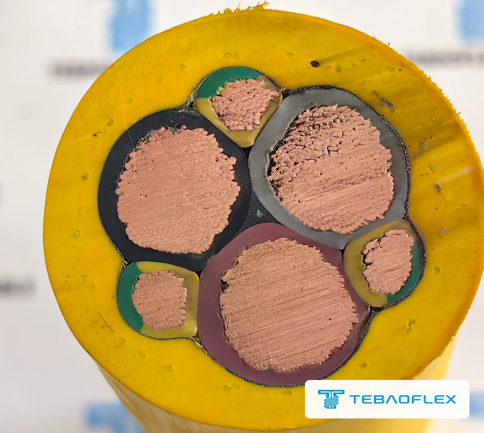
Which mining and tunneling reeling cables resist corkscrew failure by duty class?
Match the replacement cable family to your voltage class, drum geometry, and abrasion environment:
| Equipment and reeling duty | Torsion and tensile reinforcement | Reference cable specifications |
|---|---|---|
| Underground LHD scooptrams and face loaders (0.6/1 kV, tight drums + rock floor) | Anti-torsion braid + abrasion-resistant 5GM5 rubber or cut-resistant 11Y TPU outer jacket | NTSKCGWÖU-kon 0.6/1 kV Reinforced Loader Reeling Cable, (N)TMH3S 0.6/1 kV Heavy TPU Mining Reeling Cable and 0.6/1 kV Heavy-Duty PUR Reeling Cable with 2 Pilot Cores |
| Vertical blast-hole drill masts and multi-sheave rotary rigs (600–2000 V) | Short-pitch lay + high-flex mast reinforcement engineered for vertical hanging weight and top-head pulley travel | 600/2000 V Blast-Hole Drilling Mast Reeling and Festoon Cable |
| Tunnel-boring machines (TBMs), roadheaders and MV mobile substations (3.6/6 to 20/35 kV) | DIN VDE 0250-813 dual elastomer sheath with vulcanized anti-torsion W braid and semiconductive/tinned-copper core screens | (N)TSCGECWÖU Medium-Voltage TBM Reeling Cable, (N)TSCGEWÖU 3.6/6–18/30 kV Mine Reeling and Distribution Cable and (N)TSCGEWTÖUS High-Speed Anti-Torsion MV Reeling Cable |
| Automated stacker-reclaimers, shovels and MV fibre-composite reels (AS/NZS 2802) | Anti-torsion medium-voltage reeling build protecting integrated single-mode or multimode optical fibres | AS/NZS 2802 Type 440F and Type 450F 3.3–22 kV Fibre-Optic Reeling Cable |
On automated port cranes and reclaimers carrying integrated 12FO or 24FO optical subunits, axial twist pinches loose buffer tubes before copper cores fail — see our guide to specifying +FO and FC-PNCT fiber-optic composite reeling cables.
What to measure on your reel before ordering a replacement cable
Send these six field parameters alongside photos of the corkscrewed section and guide path so we can verify whether a reinforced anti-torsion construction or a roller adjustment is needed:
- Reel type and drive control: Monospiral, level-wind cylindrical, or random-wound; spring, hydraulic motor, constant-torque stall drive, or variable-torque VFD reel.
- Drum and sheave dimensions: Empty barrel diameter, full flange diameter, drum width between flanges, and every guide roller diameter along the route.
- Route angles and bends: Distance from the level-wind or fixed guide funnel to the drum (to verify fleet angle ≤ 1.5°–2°), any reverse S-bends, and center-to-center spacing between sheaves.
- Travel kinematics: Total payout length, dead wraps left at full travel, vertical hanging drop, travel speed (m/min), and acceleration (m/s²).
- Electrical duty and gland limits: Voltage U₀/U, phase/earth/pilot/fibre core count, wound layers under load, and minimum/maximum gland seal diameter.
- Exact location of the corkscrew: Metres from the machine anchor or drum entry where twisting starts, plus stripped core photos to confirm true copper size.
As of August 2026, the minimum order is 50 m for standard and customised constructions alike, and lead time runs from 7 to 45 working days depending on product type, stock position and customisation. Send your reel dimensions and cable specification for an anti-torsion engineering check.
Questions
What causes a reeling cable to corkscrew on a drum?
A reeling cable corkscrews when axial torsion accumulates faster than the cable construction can resist it. The four main causes are pulling cable off over a stationary drum flange during installation (adding one 360-degree twist per turn), excessive fleet or lateral entry angles above 1.5 to 2 degrees on level-wind drums (or above 5 degrees at guide funnels), reverse S-bends spaced closer than 20 times cable diameter, and pulling tension exceeding 15 to 20 N/mm² on a cable that lacks an embedded anti-torsion braid.
Can a corkscrewed or birdcaged reeling cable be untwisted and reused?
No. Once visible helical corkscrewing, Z-kinking or localized jacket birdcaging appears, the copper conductors inside have already undergone plastic elongation and buckling relative to the elastomeric sheath. Untwisting the cable by hand only masks the surface wave briefly while accelerating strand breakage and phase-to-earth insulation failure on the next reeling cycles; the deformed length must be cut out or replaced.
What is the maximum fleet angle for a level-wind or monospiral cable reel?
On cylindrical level-wind drums, keeping the fleet angle between the guide roller and the drum flange within 1.5 to 2 degrees ensures clean turn-by-turn stacking without side-wall climbing and rolling torsion. Where a cable enters or leaves a guide funnel or drum under IEC 60204-1 clause 13.4.3, the lateral deflection angle must never exceed 5 degrees.
How many dead wraps must remain on a cable reel to prevent anchor twist and pull-out?
At least two full dead wraps must remain on the reel barrel at maximum machine travel under IEC 60204-1 and PEMA reeling guidelines, and two full turns are likewise required on any fixed-end tension-relief drum. Running down to the bare gland clamp transfers full dynamic pull and torsional shock directly into the entry termination.
Does an embedded anti-torsion braid make a replacement reeling cable thicker?
No. In DIN VDE 0250-813 and 0250-814 reeling constructions, the open-weave polyamide or aramid anti-torsion braid is vulcanized directly into the interface between the inner and outer elastomer sheaths. Because the outer compound flows through the open mesh during tandem vulcanization, the finished cable stays within the standard nominal outside diameter for existing drum grooves and glands.
How do you check whether a newly installed reeling cable is accumulating twist?
Chalk a straight longitudinal reference line along the unreeled jacket—or track the factory sheath print—over five to ten slow commissioning travel cycles before full production. Note that a gentle factory print helix over long lengths is normal manufacturing drift, whereas a line whose spiral pitch tightens progressively with every reel cycle proves that the guide rollers, S-bend or anchor clamp is injecting live torsion.