









Dynamic Crane Fieldbus & Composite Reeling Engineering · 0.6/1 kV
A CAN-BUS crane reeling cable or hybrid PROFIBUS L2 festoon cable combines low-voltage power and control conductors with an individually shielded, controlled-impedance copper data pair inside a single dynamic outer jacket. Getting that composite right demands more than slipping a stationary plant bus wire into a multi-core rubber bundle: fine-stranded IEC 60228 flexible conductors, low-loss polyethylene (PE) bus insulation, a flex-enduring ≥ 80 % tinned-copper braid and compacted concentric symmetry must all work together so fieldbus communication stays glitch-free across hundreds of thousands of reel and trolley cycles.
Why do stationary armored control or plant fieldbus cables fail on crane reels and festoons?
Modern container spreaders, shipboard cranes, gantry trolleys and overhead process cranes exchange real-time twist-lock feedback, load-cell weight readings, anti-sway encoder telemetry and VFD fault codes over serial fieldbus lines running alongside 0.6/1 kV auxiliary power and control wiring. Attempting to route a fixed Class 2 XLPE/PVC/SWA control cable—or lashing a rigid solid-core stationary PROFIBUS cable onto an existing power cable—triggers two fast failures:
- Mechanical fatigue and corkscrewing: Rigid Class 2 copper strands and steel wire armor work-harden and fracture under continuous cyclic reel winding or festoon loop flexing (see our reeling cable corkscrew failure analysis and reeling cable selection guide).
- Foil-screen cracking and impedance reflections: Stationary industrial bus cables rely on thin aluminum/polyester tape shields and solid single-wire copper conductors. Repeated bending over crane guide sheaves creases the foil, opens hairline gaps in high-frequency EMI coverage and flattens the twisted pair geometry—shifting characteristic impedance away from 120 Ω or 150 Ω and causing erratic bus-off alarms whenever nearby hoist motors start.
How do integrated CAN-BUS, PROFIBUS L2 and RS-485 hybrid crane constructions compare?
Although crane PLC networks share differential twisted-pair signaling, their target characteristic impedances (IEC 61158 fieldbus profiles and ISO 11898 CAN standards), conductor gauges and capacitance budgets are not interchangeable. Substituting a 120 Ω CAN-BUS pair on a high-baud 150 Ω PROFIBUS-DP segment introduces signal reflections that limit baud rate and cable length.
| Specification parameter | Integrated CAN-BUS (ISO 11898) | Integrated PROFIBUS-DP / L2 | Integrated RS-485 / Modbus Pair |
|---|---|---|---|
| Nominal characteristic impedance | 120 Ω (±10 % typical at 1 MHz) | 150 Ω (±15 Ω at 3–20 MHz) | 120 Ω (±12–15 Ω at 1 MHz) |
| Typical flexible bus gauge | 2 × 0.24 mm² to 2 × 0.5 mm² (stranded Cu / CuSn) | 2 × 0.34 mm² to 2 × 0.5 mm² (flexible stranded) | 2 × 0.25 mm² to 2 × 0.75 mm² (fine-stranded CuSn) |
| Dielectric insulation | Solid or cellular polyethylene (PE, εr ≈ 1.5–2.3) | Foamed / skin-foam PE (low capacitance ≤ 30 nF/km) | PE or foamed PE (typically 40–55 nF/km) |
| Dynamic EMC shield construction | Tinned-copper wire braid ≥ 80 % optical coverage (+ optional flex foil) | Flexible foil/fleece + dense tinned-copper wire braid ≥ 80–85 % | Tinned-copper wire braid ≥ 80 % optical coverage |
| Typical crane application | Spreader twist-locks, jib load-moment indicators, mobile crane reels | Gantry trolley PLC I/O, festoon automation loops, torsion baskets | Hoist diagnostics, weighbridge/sensor telemetry, marine cranes |
| TEBAOFLEX reference family | XTRM (N)SHT11Y PUR Crane Spreader | PROFIBUS L2 Crane Festoon Torsion Bus | Marine & Industrial Fieldbus Series |
How do conductor stranding, PE dielectric and ≥ 80 % CuSn braid prevent bus dropouts near power cores?
Inside a compact 0.6/1 kV composite crane cable—for example, 37 × 2.5 mm² power and control conductors sharing the same polyurethane sheath with one 2 × 0.24 mm² CAN-BUS twisted pair—the data conductors sit millimeters away from switching contactor coils and inverter-fed auxiliary motors. Maintaining bit-error-free communication under motion requires four coordinated layers of protection:
- Controlled low-permittivity PE dielectric: Standard PVC or thick EPR rubber insulation exhibits higher dielectric constant (εr ≈ 3.5–5.0) and dielectric loss than polyethylene (εr ≈ 2.3), increasing mutual capacitance and shrinking allowable bus run length. Insulating the bus conductors in precision-extruded PE keeps impedance locked near 120 Ω or 150 Ω even across wide port temperature swings.
- Short, uniform pair twist length: Differential bus receivers reject common-mode electromagnetic noise only when both wires of the pair see identical induced voltage. A tight, consistent lay length inside the bus element preserves balance as the cable bends around guide sheaves.
- High-coverage woven tinned-copper wire braid (≥ 80 %): Unlike foil-only screens that tear under repetitive reeling, a braided CuSn shield resists mechanical fatigue and delivers low transfer impedance at switching harmonics (for deeper EMC grounding physics on inverter-fed drives, see our double-screened VFD cable and 360-degree EMC termination guide).
- 360-degree termination and correct end-of-line resistors: Clamp the bus braid cleanly at the crane junction-box EMC bar rather than twisting long pigtail drain wires, and verify that 120 Ω (CAN-BUS) or active 150 Ω (PROFIBUS) termination resistors sit only at the two physical ends of the trunk—never at intermediate festoon drops.
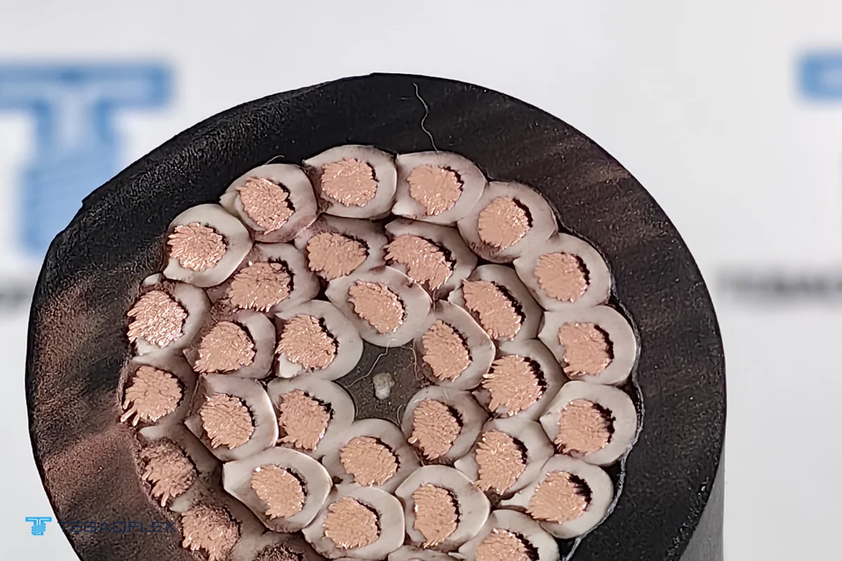
How do engineers compact high-core hybrid crane cables into strict reel-groove and gland OD windows?
Crane retrofits rarely allow operators to replace cast-steel sheaves, cable-reel flanges or bulkhead entry glands just because a hybrid replacement cable grew 3 mm thicker than the original drawing. When a high-core bundle combines dozens of 2.5 mm² conductors with a shielded fieldbus unit, naive over-sheathing quickly pushes outer diameter past physical clearance limits.
On our delivered UAE 200 m NSHT11Y 37×2.5 mm² + CAN-BUS crane reeling replacement case, the standard double-sheathed calculation reached ~30.0 mm OD while the existing crane routing enforced a hard 27.0 mm ceiling (with the initial unjacketed core bundle already at 25.9 mm). By tightening concentric stranding fill factors around the central tensile support core, nesting the ≥ 80 % braided PE CAN-BUS pair cleanly inside the inner core ring to eliminate radial bulges, and switching to a dense, high-modulus polyurethane outer sheath, factory production met the 27 ± 0.5 mm target—caliper-verified across three axes at 27.01 mm, 26.95 mm and 26.93 mm. Similarly, on flat festoon tracks where width clearance governs saddle clamps, engineers can place shielded bus units symmetrically along the neutral bending plane (detailed in our flat cable vs round cable crane selection guide).
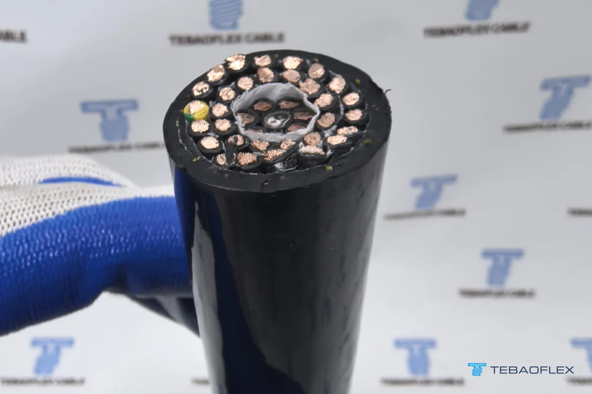
When should port crane engineers choose copper CAN-BUS / PROFIBUS hybrids versus integrated fiber optics (+FO)?
Both copper fieldbus hybrids and optical composite reeling cables eliminate separate festoon drops or slip-ring interference headaches, yet each dominates a distinct voltage, distance and bandwidth envelope across port and container crane cable packages:
| Selection criterion | Copper Fieldbus Hybrid (CAN-BUS / PROFIBUS L2) | Fiber-Optic Composite Reeling (+FO / LWL) |
|---|---|---|
| Typical system voltage | Low voltage 0.6/1 kV (spreaders, jibs, control reels, festoons) | Low voltage or medium voltage 3.6/6 kV to 12/20 kV (STS, RMG, unloaders) |
| Practical dynamic run length | Short to medium runs (typically ≤ 100–250 m depending on baud rate) | Long crane runway reels (200 m to 1,000+ m with negligible attenuation) |
| EMI & high-voltage surge immunity | High with ≥ 80 % CuSn braid + 360° bonding; still metallic | Complete galvanic isolation — immune to MV switching and lightning surges |
| Termination & field maintenance | Standard screw/cage-clamp PLC blocks; no optical splicers or media converters | Requires optical splice tray / connectors + 1,500–2,000 mm breakout tails + converters |
| Bandwidth & future telemetry | Deterministic PLC I/O, encoders, twist-locks and safety interlocks (kbps–12 Mbps) | Multi-gigabit Ethernet, automated crane LiDAR, HD CCTV and redundant rings |
| Key TEBAOFLEX reference | UAE 27 mm NSHT11Y + CAN-BUS Case · PUR-C-HF EMC Cable | Fiber-Optic Composite (+FO) Reeling Guide |
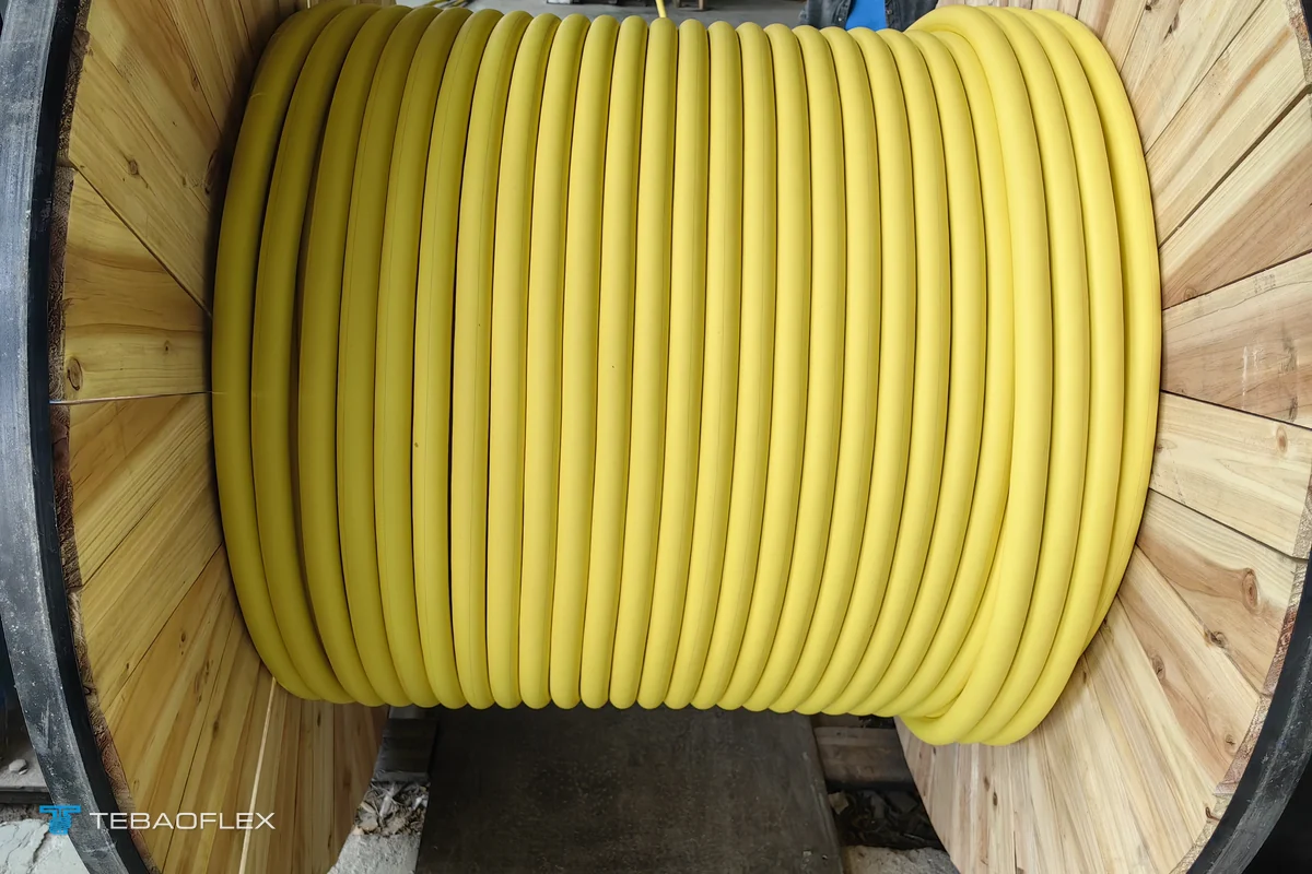
What 6 parameters lock in a trouble-free hybrid crane bus cable order?
Before releasing a purchase order for a composite power-and-fieldbus crane cable (or evaluating an alternative to standard (N)SHTÖU rubber reeling lines and PUR-C-HF screened crane feeders), verify six concrete engineering inputs:
- Exact motion geometry: Distinguish cylindrical multi-layer reel, monospiral reel, vertical spreader basket, torsional reel or C-rail/I-beam festoon trolley—each dictates different tensile braid and lay-length engineering.
- Bus protocol, baud rate & impedance: Confirm whether the PLC network runs 120 Ω CAN-BUS (ISO 11898), 150 Ω PROFIBUS L2/DP, 120 Ω RS-485 or 100 Ω Industrial Ethernet, plus maximum run length at target baud rate.
- Power & control conductor schedule: List phase count, cross-section, voltage rating (0.6/1 kV), protective earth layout and whether variable-frequency drives share the same cable jacket.
- Hard maximum OD & minimum bending radius: Measure existing reel groove width, guide roller radius and gland bore so compacting targets (such as 27.0 mm max) are engineered before extrusion tooling is cut.
- Outer sheath polymer & environment: Choose halogen-free polyether PUR (11Y / 11Y-HF) for tight ODs, abrasion and salt-spray ports, or thermoset CR/5GM5 rubber where welding spatter or elevated coiled-layer heat dominates.
- Continuous length, spare margin & lead time: Confirm exact continuous meters per drum without mid-span splices; TEBAOFLEX manufactures custom hybrid crane cables from a 50 m MOQ with 7 to 45 working-day production schedules. Send your crane cable core schedule and OD ceiling to TEBAOFLEX engineers for a custom cross-section layout and quotation.
Frequently asked questions
Why do standard fixed PROFIBUS or CAN-BUS cables fail quickly when strapped to a crane reel or festoon?
Fixed plant fieldbus cables typically use solid single-wire copper conductors, rigid foam dielectrics and foil-heavy shields designed for stationary trays. Continuous drum bending and festoon trolley flexing work-harden solid conductors, crack aluminum foil tapes and deform the pair spacing—causing characteristic impedance discontinuities (reflections) and intermittent PLC communication trips long before the power cores fail.
How does a hybrid crane cable keep 120 Ω CAN-BUS or 150 Ω PROFIBUS L2 impedance stable inside a multi-core power bundle?
Hybrid reeling and festoon designs use finely stranded flexible copper bus conductors insulated with low-loss solid or skin-foam polyethylene (PE), twisted to a controlled tight lay length and bound beneath a protective tape and high-coverage (≥ 80 %) tinned-copper wire braid. Positioning the screened bus element symmetrically in the concentric lay or neutral festoon plane shields it from radial crushing between adjacent 2.5 mm² or larger power cores.
Why is a tinned-copper wire braid (≥ 80 % coverage) preferred over aluminum foil alone on dynamic crane bus pairs?
Pure aluminum/polyester foil offers high optical coverage when stationary, but repeated reel winding and crane-boom torsion crease thin foil into hairline cracks that break high-frequency shield continuity. A woven tinned-copper wire braid with at least 80 % optical coverage flexes over hundreds of thousands of cycles without tearing, maintains low transfer impedance against nearby VFD switching noise and terminates reliably in 360-degree EMC glands.
When should a crane specify integrated copper CAN-BUS / PROFIBUS L2 versus integrated fiber optics (+FO)?
Copper fieldbus pairs (120 Ω CAN-BUS, 150 Ω PROFIBUS L2 or RS-485) are generally preferable on 0.6/1 kV spreader baskets, jib cranes and low-voltage festoon runs under roughly 150 to 250 m where direct copper termination to crane PLCs, load cells and encoders avoids active optical media converters. Switch to integrated fiber-optic composite reeling cables (+FO) for longer travel distances, medium-voltage (3.6/6 kV to 12/20 kV) reels, high-bandwidth CCTV/automation telemetry or extreme inverter EMI.
How tightly can a high-core hybrid power and CAN-BUS crane reeling cable be compacted for narrow sheaves?
High-core-count hybrids such as 37 × 2.5 mm² plus a screened CAN-BUS pair can often be compacted by 2 to 3 mm below standard dual-sheath baselines by optimizing concentric stranding lay lengths, balancing the bus unit within the inner core layer and extruding a dense, high-tear-strength polyurethane (PUR) outer sheath—as verified on our UAE 200 m NSHT11Y + CAN-BUS delivery compacted from ~30 mm to 26.93–27.01 mm OD.
What details should crane engineers include when requesting a custom hybrid fieldbus reeling or festoon cable?
Specify the dynamic duty (monospiral reel, cylindrical multi-layer reel, vertical basket or festoon trolley), exact power/control core count and cross-section, bus protocol and impedance (120 Ω CAN-BUS, 150 Ω PROFIBUS L2 or Ethernet), hard maximum outer diameter imposed by existing sheaves and glands, travel speed, minimum bending radius and continuous drum length (TEBAOFLEX builds custom hybrids from a 50 m MOQ in 7 to 45 working days).