









Site receiving and testing
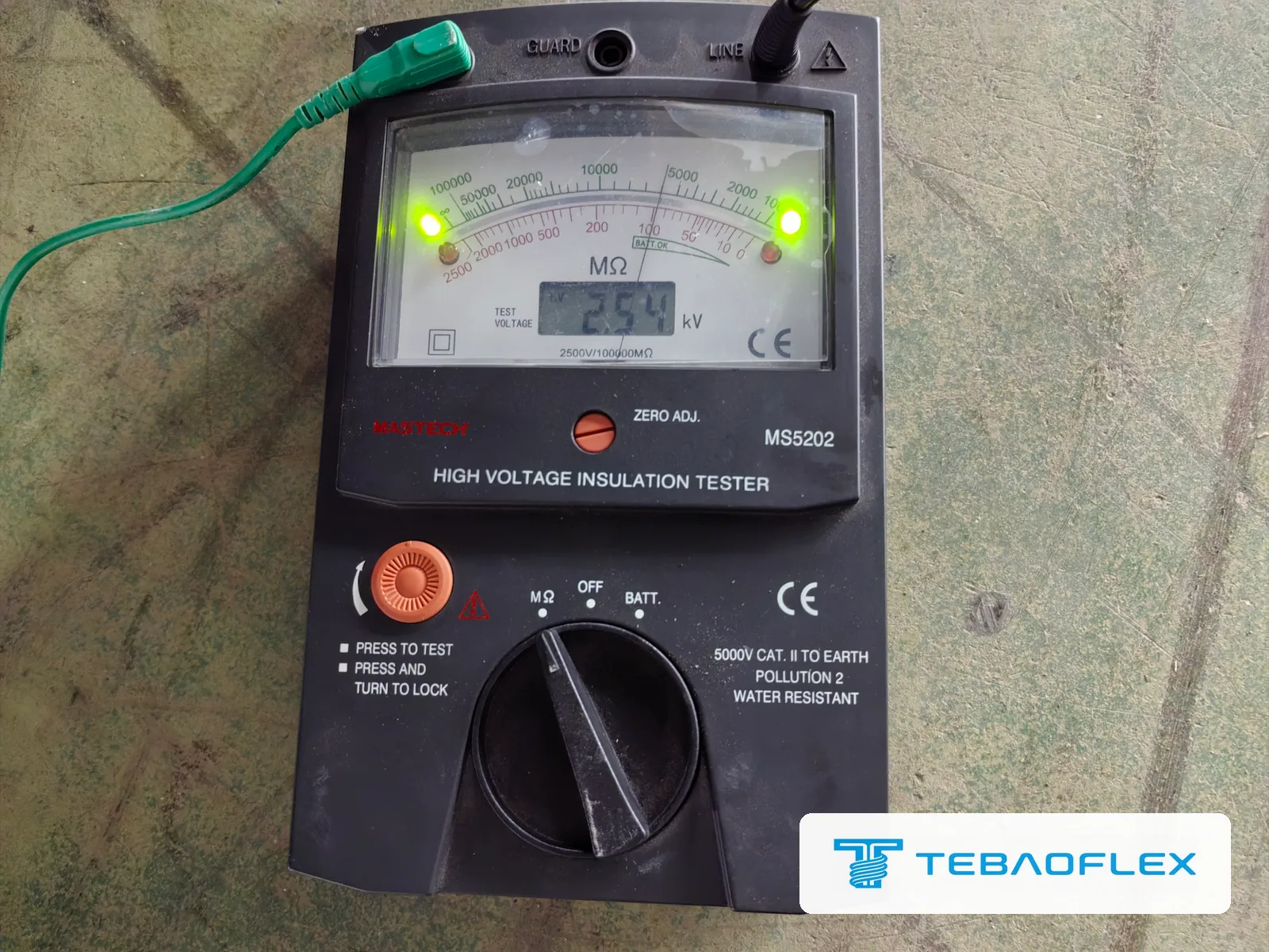
When a new mining cable drum arrives at the mine warehouse, inspect the flanges, battens and heat-shrink end caps before signing the carrier receipt, then run a 1-minute baseline Megger insulation-resistance (IR) test at 1,000 V DC (600 V–1 kV cables), 2,500 V DC (1.1–5 kV), or 5,000 V DC (over 5 kV per ANSI/NETA ATS and IEEE 43), correct readings to 20 °C, verify phase-to-phase symmetry within 20 % to 30 %, and discharge every tested core to earth for at least 4 × test duration. Logging these figures before shaft lowering or reel spooling catches transit moisture and forklift crush damage before couplers are fitted.
How does site arrival inspection differ from a cable factory acceptance test?
A factory acceptance test (FAT)—including 5-minute AC high-voltage withstand and partial discharge screening down to 10 pC—proves dielectric integrity before the drum leaves the manufacturer’s test bay, as detailed in our guide to routine, sample and type tests in a cable FAT and shown in our customer factory visit for 11 kV and 33 kV EPR cable testing. Between the factory gate and an underground mine store, however, ocean containers sweat, port forklifts strike wooden lags, and crane slings can squeeze drum flanges inward onto the top cable layer.
A receiving inspection at the mine warehouse serves three practical engineering purposes before carrier sign-off or underground lowering:
- Transit damage isolation: Separates shipping-container forklift impacts, broken flange bolts, or torn end caps from damage caused later during shaft clamping or haulageway pulling.
- Pre-installation dielectric baseline: Establishes a temperature-corrected MΩ·km benchmark on the untouched reel so commissioning electricians have a direct reference after couplers or splice kits are installed.
- Moisture prevention in storage: Identifies punctured heat-shrink end caps immediately so cable ends can be dried and resealed before capillary action draws rainwater into fine Class 5 tinned copper strands or paper/elastomer fillers.
What should you inspect on the drum before touching a test lead?
Never unlag or strip a cable end until external packaging evidence is photographed alongside the drum stencil and bill of lading:
- Drum posture and flange integrity: Confirm the drum arrived upright on its flanges—never laid flat on its side, which tangles layers and forces over-flange twist (see why improper drum handling causes reeling cable corkscrew failure). Check steel or wooden flanges for inward bowing, protruding nails, or crushed outer battens pressing into the top wrap.
- Both cable ends and heat-shrink end caps: Both the outer tail and the inner barrel tail (brought out through the flange slot) must carry intact, adhesive-lined heat-shrink caps. Squeeze each cap gently: water droplets, white salt crust, or a loose slip-fit cap demands stripping back 150 to 300 mm to inspect for moisture wicking inside the core interstices.
- Sheath legend and consecutive metre marks: Verify voltage rating (U₀/U), conductor count and cross-section, standard designation, and start/end metre numbers (L_end – L_start) against your purchase order.
Which Megger DC test voltage matches your mining cable rating?
Applying too low a DC voltage (such as a 250 V multimeter check on a 6.6 kV feeder) fails to stress damp tracking paths, whereas applying 5,000 V DC to a 300 V mine telephone cable can overstress thin control insulation. Follow published field maintenance selections from ANSI/NETA ATS, IEEE Std 43, and IEC 60364-6:
| Cable rated voltage class | Typical mining cable examples | Recommended Megger DC voltage | Test duration |
|---|---|---|---|
| Up to 300 V / 500 V (intrinsically safe, telecom, thermocouple) | MHYV, MHSYV-5, MKVV, instrumentation pairs | 250 V to 500 V DC | 1 minute spot reading |
| 600 V to 0.6/1 kV (up to 1.14 kV low voltage) | NTSKCGWÖU 0.6/1 kV, (N)TMH3S, TECK90, MY/MYP, Type W 600 V | 1,000 V DC (500 V DC minimum under IEC 60364-6) | 1 minute spot reading |
| 1.1/1.1 kV to 5,000 V (2 kV portable and 3.3 kV face cables) | Type G-GC 2000 V, SHD-GC 2–5 kV, AS/NZS 1972 Type A/B 1.1 kV, 1.9/3.3 kV shearer cables | 2,500 V DC | 1 minute spot (optional 10 min PI on long feeders) |
| Above 5 kV up to 35 kV (medium-voltage shaft, tunnel and shovel cables) | Type MP-GC / MPF-GC 5–35 kV, MYJV22/32 6–10 kV, AS/NZS 1972 11/22 kV, 35-CHVU 20/35 kV | 5,000 V DC (or 2,500 V to 5,000 V DC per site meter spec) | 1 minute spot + 10 min / 1 min Polarization Index (PI) |
How to wire Line, Earth and Guard terminals—and discharge stored drum energy safely
To measure one phase conductor cleanly on a screened or armoured mining cable drum, prepare dry, clean 75 to 120 mm stripbacks at both the inner and outer drum ends, keep the far-end conductors separated in air well clear of wet timber or steel flanges, and connect all non-tested phases, metallic core screens, grounding conductors, and wire/tape armour together to the grounded Earth (E / + depending on instrument convention) bus.
Two field precautions prevent false failures and electric shock during arrival testing:
- Always use the GUARD terminal on 2.5 kV and 5 kV tests in humid mine yards: Wrap two tight turns of clean bare copper wire around the exposed EPR or XLPE insulation halfway between the bare copper conductor and the cut-back semiconductive screen, and clip the Megger GUARD lead to that wrap. Surface leakage across morning dew or coal dust then bypasses the meter’s current-measuring shunt instead of masquerading as bulk insulation failure.
- Treat a charged cable drum like a high-voltage capacitor bank: A 500 m medium-voltage screened drum has roughly 0.15 to 0.40 µF of phase-to-screen capacitance. After switching off the DC test button, let the instrument bleed the core to 0 V before unclipping leads, then apply a rated grounding lead bonding the tested copper to screen/earth for at least 4 × the test duration (4 minutes minimum after a 1-minute test; 40 minutes after a 10-minute PI test) so absorbed polarization charge cannot rebound to hundreds of volts.
How do length, temperature and three-phase balance decide pass or investigate?
A common receiving mistake is comparing a raw handheld Megger number on a 600 m drum sitting in 38 °C tropical sun directly against a 20 °C per-kilometre datasheet constant. Three physical relationships govern every cable IR measurement:
- Length scaling (MΩ·km): Because radial insulation leakage paths act in parallel along every metre of cable, doubling length cuts measured megohms in half. Convert any measured drum reading R_meas (MΩ) on length L (km) to kilometric insulation resistance via IR_km (MΩ·km) = R_meas × L.
- Temperature correction to 20 °C: Polymeric insulation resistance drops steeply with heat—roughly halving for every 10 °C rise above 20 °C across typical ambient warehouse temperatures (exact K_T tables in IEEE Std 43 and ICEA standards vary slightly between EPR and XLPE).
- IEEE / NETA floor versus three-phase symmetry: For field maintenance screening where the cable standard or contract does not specify a higher acceptance constant, IEEE Std 422 / 525 and ANSI/NETA ATS cite the length-adjusted reference floor below:
Field reference floor at 20 °C: R_min (MΩ) = (Rated kV + 1) × 305 ÷ Length (m) [or (kV + 1) × 1,000 ÷ Length (ft)]
| Example drum on arrival | IEEE / NETA 20 °C minimum floor | Typical dry new EPR / XLPE reading | When to stop and investigate even above the floor |
|---|---|---|---|
| 300 m of 0.6/1 kV loader or feeder cable (tested at 1,000 V DC) | about 2.0 MΩ (at 20 °C) | Hundreds of MΩ to several GΩ | Any phase below tens of MΩ, or one core reading > 30 % lower than the other two on the same drum |
| 300 m of 2 kV SHD-GC / Type G-GC cable (tested at 2,500 V DC) | about 3.1 MΩ (at 20 °C) | Hundreds of MΩ to several GΩ | Asymmetric L1 / L2 / L3 spread (for example 1,800 MΩ, 1,750 MΩ, and 95 MΩ—classic wet outer interstice under torn cap) |
| 500 m of 11 kV EPR or XLPE shaft feeder (tested at 5,000 V DC) | about 7.3 MΩ (at 20 °C) | Thousands of MΩ (multi-GΩ) | Polarization Index PI = R_10min ÷ R_1min < 2.0 (unless 1-min IR already exceeds 5,000 MΩ where meter leakage dominates) |
Notice why three-phase symmetry on the same reel is your sharpest diagnostic tool: L1, L2, and L3 were extruded from the same compound batch, sit at the exact same drum temperature, and have identical length. If L1 and L2 read 2,400 MΩ while L3 reads 110 MΩ, L3 technically clears the generic IEEE floor yet clearly took moisture or pinch damage—strip back 300 mm, guard the surface, and retest before accepting the drum for underground installation.
Checking pilot/earth continuity and resealing cut ends for storage
Before closing out the arrival log, run two final low-voltage checks and immediately reseal the cable:
- Phase, earth, screen and pilot continuity: Using a calibrated low-resistance ohmmeter, verify end-to-end continuity on all phase cores, split ground conductors, metallic phase screens, and the ground-check (GC) pilot core against the 20 °C loop baselines in our mining trailing cable ground-check troubleshooting guide. Test the insulated pilot core to earth at 500 V DC while no termination diode is attached.
- Immediate adhesive heat-shrink resealing: Never leave stripped test tails taped only with PVC electrical tape in an outdoor yard or humid shaft collar. Cut off the 100 mm test stripback cleanly, slide on a heavy-wall adhesive-lined polyolefin heat-shrink end cap sized to the outer jacket, shrink from the closed tip back toward the sheath until hot-melt adhesive flows 360° around the rim, and re-fasten wooden drum battens if the drum goes back into spare storage.
Underground shaft, armoured feeder and high-voltage trailing cable datasheets
Compare construction layers, screen types, and governing test standards across our stationary mine feeder and high-voltage trailing families—and state in your enquiry which routine drum test records or witnessed inspections your project contract requires:
| Mine installation zone | Insulation, screen and armour architecture | Reference cable datasheets |
|---|---|---|
| North American borehole, shaft and substation power feeders (5–35 kV) | EPR insulation, copper tape/wire core shields, ground-check core; unarmoured CPE (MP-GC) or galvanized steel wire armour (MPF / MPF-GC) | Type MP-GC 5–35 kV EPR/CPE Mine Power Feeder Cable and Type MPF and MPF-GC Armoured Vertical Shaft Feeder Cable |
| Australian and New Zealand underground fixed distribution (AS/NZS 1972) | 1.1/1.1 kV elastomeric Type A/B feeders, 11–22 kV XLPE wire-armoured feeders, and elastomeric replacements for legacy paper-insulated 11 kV feeders | AS/NZS 1972 Type A and Type B 1.1/1.1 kV Mine Feeder Cable, AS/NZS 1972 11 kV and 22 kV XLPE Armoured Mine Feeder and AS/NZS 1972 11 kV Paper-Insulated Feeder Replacement |
| Coal roadway, incline and vertical shaft armoured power (MT 818 / GOST / PN-G) | Steel tape armour (MYJV22, ВБбШвнг(А)-LS) for horizontal galleries vs heavy round wire armour (MYJV32, YHKGYFoyn) for vertical/steep shafts | MYJV, MYJV22, MYJV32 and MYJV-GXT XLPE Mine Power Cable, ВБбШвнг(А)-LS GOST Low-Smoke Armoured Mine Cable and YHKGYFoyn 3.6/6 kV Screened Armoured Shaft Cable |
| Open-pit 20/35 kV electric shovels, draglines and mobile substations | Extra-thick EPR dielectric with semiconductive and composite metallic phase screens for high-voltage trailing service | 35-CHVU 20/35 kV High-Voltage Mining Trailing Cable |
When preparing a tender or purchase order, list the product standard, drum cut lengths, maximum flange dimensions for your shaft cage or store crane, and the exact factory test records your site commissioning team needs. As of August 2026, the minimum order is 50 m for standard and customised constructions alike, and lead time runs from 7 to 45 working days depending on product type, stock position and customisation. Send your mine feeder or trailing cable schedule and required test list for quotation.
Questions
What Megger DC voltage should be used to test a new mining cable on arrival?
Under ANSI/NETA ATS and IEEE 43 field testing conventions, select 500 V DC for control and instrumentation cables rated up to 300 V, 1,000 V DC for low-voltage mining cables rated 600 V to 1 kV, 2,500 V DC for cables rated 1.1 kV to 5 kV (including 2,000 V Type G-GC and SHD-GC), and 5,000 V DC for medium-voltage mining cables rated above 5 kV up to 35 kV.
What is an acceptable insulation resistance reading on a new mining cable drum?
Insulation resistance scales inversely with length and halves roughly every 10 °C rise in temperature. IEEE 422 and ANSI/NETA ATS give a conservative field floor of R_min (MΩ at 20 °C) = (Rated kV + 1) × 305 ÷ Length (m), yet a dry new EPR or XLPE drum of 200 to 500 m normally reads hundreds to thousands of megohms. Equally important on a new reel is phase-to-phase symmetry: if one core reads more than 20 % to 30 % below the other two on the same drum, inspect both cut ends for moisture under the end cap.
Why does a long cable drum show a lower Megger reading than a short cut piece?
Radial insulation leakage paths act in parallel along every metre of conductor, so doubling the cable length halves the measured megohm reading. To compare drums of different lengths—or to compare a site reading against a per-kilometre datasheet value—multiply measured megohms by cable length in kilometres: IR_km (MΩ·km) = R_measured (MΩ) × L (km).
What does the Guard terminal on a 5 kV insulation tester do during a cable reel test?
Connecting the Megger Guard (G) lead to a bare copper wire wrapped tightly around the exposed insulation surface between the conductor lug and the peeled-back semiconductive screen diverts humid or dusty surface leakage current away from the meter’s measurement amplifier. Without a Guard wrap in damp mine yards, surface condensation across a 50 mm stripback can drag a multi-gigohm cable down to tens of megohms.
How long must a medium-voltage mining cable drum be discharged after a Megger test?
Industry safety standards require discharging each tested phase conductor through a rated discharge resistor and then bonding it solidly to the grounded metallic screen and earth for at least four times the DC test voltage application time—meaning at least 4 minutes after a 1-minute spot test and at least 40 minutes after a 10-minute Polarization Index test—because dielectric absorption can rebuild dangerous recovery voltage on an open conductor.
Does an arrival Megger test replace a factory high-voltage acceptance test?
No. A handheld 1 kV to 5 kV DC Megger test checks for gross transit crush damage, punctured sheaths, and moisture entry through torn end caps on arrival at the mine store. Proving full dielectric strength and void-free insulation requires the factory AC withstand and partial discharge routine tests carried out before shipment.