









Mine electrical troubleshooting
To troubleshoot a mining trailing cable ground-check (GC) or pilot-loop trip, lock out the feeder, unplug the trailing cable at the power center, and fit the relay manufacturer’s matched termination test plug across the receptacle GC and G pins: if the monitor still fails to reset, the fault is inside the power center; if it resets cleanly, divide the couplers, cable pilot loop and machine end-of-line diode step by step. Most mine monitors trip when loop resistance rises above 15 to 45 Ω, when moisture shunts pilot to earth, or when the end-of-line termination opens.
How do you isolate a ground-check trip between the power center and the cable?
A fail-safe ground-check or earth-continuity relay watches a closed low-voltage loop that travels from the power center or gate-end box out through the insulated pilot core, passes through an end-of-line device bolted to the mobile machine frame, and returns along the cable grounding conductors. Under 30 CFR 75.803 and Australian/New Zealand AS/NZS 2081 principles, the breaker must open both on an open pilot/ground path and on a direct pilot-to-ground short outby the termination device. Separating the substation from the cable first avoids hours of unnecessary cable handling.
Always perform isolation under full lockout/tagout with phase conductors proved dead and discharged. Never bridge GC directly to G with bare copper wire on a diode-monitored or tuned-impedance relay—a dead short looks identical to a crushed pilot-to-earth fault and keeps a fail-safe relay tripped.
| Test step (circuit locked out) | Observed result | Fault zone confirmed | Immediate corrective check |
|---|---|---|---|
| 1. Unplug cable at power center; insert matched test termination plug across socket GC and G | Monitor still fails to reset or shows fault | Power center / gate-end box | Check monitor control fuse, CT/filter module, receptacle rear pilot lead, and relay trip-resistance calibration |
| 2. Power center resets on dummy plug; move dummy plug to far end of unplugged trailing cable | Monitor will not reset through cable | Trailing cable or in-line couplers | Disconnect in-line couplers halfway to halve the run; measure pilot-to-ground continuity and pilot-to-ground insulation resistance |
| 3. Cable passes dummy-plug test; reconnect to machine junction box | Monitor trips as soon as machine is connected | Machine termination device or entry gland | Test end-of-line diode/Zener module out of circuit, check reversed diode polarity, and inspect frame earth stud corrosion |
| 4. System resets while stationary; trips when machine trams or motor starts | Intermittent open or nuisance shunt trip | Loose pilot pin, splice strand break, or EMI/parallel earth | Gauge recessed pilot pin engagement depth, flex old splices under an ohmmeter, and check VFD shield or parallel ground paths |
Diode termination versus impedance and RF ground monitors: why diagnostic meters mislead
Before putting a meter across a disconnected cable plug, confirm which monitoring principle your substation uses. Applying the wrong test instrument is the single most common reason electricians condemn a sound trailing cable or overlook a shorted end-of-line unit.
- End-of-line rectifier or Zener diode monitors (common on North American 2 kV to 25 kV power centers and AS/NZS 2081 relays): The monitor sends low-voltage AC (capped below 96 V open-circuit under 30 CFR 75.803-1, and typically 12 to 24 V on modern solid-state relays) down the pilot core. An encapsulation-potted silicon rectifier diode or Zener assembly bolted to the machine chassis half-wave rectifies or clips the signal. If the pilot wire opens, DC return vanishes; if a rock crushes the pilot wire directly onto an internal ground or phase screen, AC appears without rectification and trips the relay. A standard digital multimeter in Resistance (Ω) mode often outputs only 0.25 to 0.4 V DC—too low to forward-bias a 0.65 V silicon junction or a 3.9 to 6.8 V Zener stack—causing a healthy machine loop to look completely open.
- Series loop-resistance / balanced-bridge monitors (common on European gate-end boxes and shearer feeds): The circuit measures calibrated loop resistance through a known machine-end resistor (for example 10 Ω to 22 Ω) plus a blocking diode. Either a rise above the upper resistance window or a drop below the minimum window triggers an instant trip.
- Pilotless or high-frequency tone / RF monitors: Used on specialized shuttle-car or legacy three-core cables without a dedicated pilot wire, injecting an audio or radio-frequency carrier onto phase or ground paths. Corroded splice sleeves, wet couplers, or variable-frequency drive (VFD) harmonic filters easily detune the carrier trap.
Whenever an end-of-line diode or Zener module stays connected at the machine during cable testing, disconnect one lead of the termination module before running a 500 V DC insulation-resistance (Megger) test on the pilot core. Applying 500 V or 1,000 V DC directly across an unprotected machine diode can puncture the semiconductor junction and create a permanent short-trip fault.
What should the pilot-to-ground loop resistance read on a healthy trailing cable?
With both ends of the trailing cable disconnected and the far-end GC pin temporarily clipped directly to the G ground pin (excluding any diode), measured DC loop resistance equals the resistance of the pilot core in series with the parallel combination of the cable grounding conductors, plus 0.05 to 0.15 Ω per mated coupler pair. Because the pilot core is much smaller than the combined ground conductors, the pilot wire accounts for 70 % to 85 % of total loop ohms.
Healthy shorted-end loop resistance R_loop ≈ L (km) × (R_pilot + R_grounds_parallel) + (0.1 Ω × coupler count)
The reference table below derives conductor DC resistance at 20 °C from IEC 60228 Class 5 tinned copper and ICEA S-75-381 flexible stranding values, and shows typical expected loop readings for a 300 m trailing cable run.
| Pilot / GC core size | Typical cable families | Max pilot DC resistance at 20 °C | Expected 300 m shorted GC-to-G loop (with 2 couplers) | Investigate splice or pin contact above |
|---|---|---|---|---|
| 2.5 mm² Class 5 tinned Cu | DIN VDE 0250 control / auxiliary pilot cores | 8.21 Ω/km | about 2.7 to 3.0 Ω | 4.5 Ω (well below 20–45 Ω relay ceiling, yet indicates high-resistance joint) |
| 4.0 mm² Class 5 tinned Cu | BS 6708 Type 43 / Type 307, European face cables | 5.09 Ω/km | about 1.8 to 2.1 Ω | 3.5 Ω |
| 10 AWG (5.26 mm²) | ICEA Type G-GC, SHD-GC (smaller AWG sizes), AS/NZS Type 241/275 | about 3.6 to 3.9 Ω/km | about 1.3 to 1.6 Ω | 2.8 Ω |
| 6.0 mm² Class 5 tinned Cu | DIN VDE NTSKCGWÖU, Polish ONGCekż shearer cables | 3.39 Ω/km | about 1.2 to 1.5 Ω | 2.5 Ω |
| 8 AWG (8.37 mm²) | ICEA Type G-GC and SHD-GC mainstream portable runs | about 2.2 to 2.4 Ω/km | about 0.9 to 1.2 Ω | 2.2 Ω |
| 6 AWG (13.3 mm²) | Large-conductor SHD-GC shovel and dragline trailing runs | about 1.4 to 1.5 Ω/km | about 0.6 to 0.9 Ω | 1.8 Ω |
Notice the wide gap between a healthy 300 m cable loop (0.6 to 3.0 Ω) and a typical relay trip setting (15 to 45 Ω). When a monitor trips on high loop resistance, you are almost never looking at normal copper length resistance—you are looking for a corroded coupler pin, a loose crimp barrel inside a cold-shrink splice, or a pilot core held together by its last two copper filaments.
Why the ground-check conductor breaks inside an intact outer jacket
In underground room-and-pillar headings and open-pit shovel benches, maintenance crews regularly find a trailing cable whose heavy elastomeric jacket looks unmarked from the outside, whose three phase conductors pass continuity, yet whose pilot loop is dead open. Two mechanical mechanisms explain why the ground-check wire fails first:
- Disproportionate tensile strain on the smallest copper core: In a 3×4/0 + 2×2 + 1×8 AWG Type G-GC or SHD-GC cable, the three phase cores total about 322 mm² of copper while the single #8 AWG pilot core has just 8.37 mm². When a shuttle car, continuous miner, or dozer pulls the cable past the 15 to 20 N/mm² working tension limit documented in our guide to mining trailing cable damage and splice rules, copper yields plastically while the elastomeric EPR/CPE or PCP layers recover elastically. On rebound, the small pilot core buckles into tight micro-waves and work-hardens until its strands snap inside intact yellow or black pilot insulation.
- Zero slack left in field splices: When an electrician rebuilds a damaged section and crimps all six conductors to identical length, the outer interstitial pilot core follows a longer helical path during bending than the neutral axis. Leaving the grounding and ground-check conductors about 6 mm (1/4 in) longer than the power conductors inside a splice keeps tensile load on the main phase copper rather than the pilot crimp.
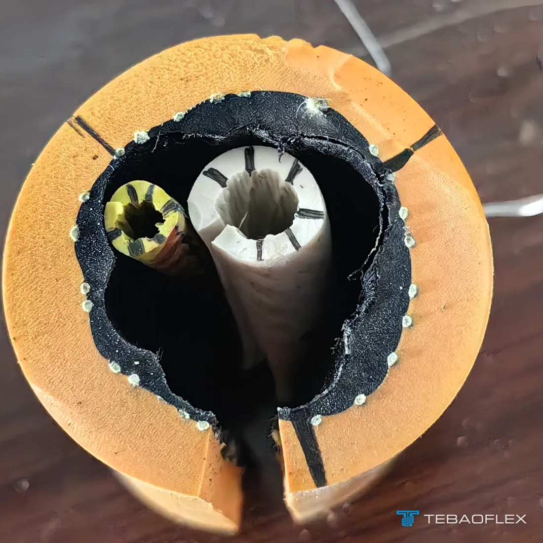
To locate a hidden internal pilot break without slicing sound jacket, isolate both ends, connect a Time Domain Reflectometer (TDR) between the GC core and the adjacent bare G ground conductor, and read the distance to the impedance spike. If no TDR is on site, measure capacitance from GC to G from End A (C_A) and from End B (C_B) with a handheld LCR meter: the open break sits at Length × C_A ÷ (C_A + C_B) from End A.
Intermittent trips during tramming or motor starting: couplers, moisture and VFD noise
Nuisance trips that clear immediately on reset are rarely random relay defects. Group them by when the breaker drops out:
- Trips when the cable moves, reels, or crosses a haulage berm: By design, the ground-check contact pin in heavy-duty mining couplers is shorter (last-make, first-break) so the main circuit de-energises before phase pins part if a coupler separates. If the coupler coupling nut backs off by 2 to 3 mm, if mud packs behind the insulator flange, or if a split socket sleeve loses spring tension, vibration momentarily breaks pilot contact. On drum-reeled loaders and jumbos, axial twist can also wind the outer interstices until the pilot core kinks—see our companion guide on reeling cable corkscrewing causes and mechanical prevention.
- Trips in wet headings or after washdown (shunt leakage fault): Saline mine water or carbon dust bridging GC to G across a damp coupler face creates a parallel leakage path ahead of the machine diode. Even 5 to 25 kΩ of wet tracking imbalances the positive/negative half-wave ratio on diode monitors. Test pilot-to-ground insulation resistance at 500 V DC (with the machine diode disconnected); a clean dry pilot core should read tens to hundreds of megohms, never kilohms. Before commissioning any newly delivered spare drum, log its baseline insulation resistance using our new mining cable arrival inspection and Megger testing procedure.
- Trips exactly on large motor inrush or VFD acceleration: High phase inrush or steep IGBT switching edges induce longitudinal voltage into an asymmetrically positioned interstitial pilot core, or drive stray ground-return current through parallel metallic paths (conveyor structure, water pipes, roof mesh) bonded between the machine and power center. Switching to a center-positioned ground-check geometry (SHD-CGC), an individually screened pilot core, or a concentric braided ground-check (CSA Type G-BGC / SHD-BGC) cancels most induced phase flux.
Which mining cable constructions protect the pilot core in harsh trailing and reeling duty?
If fault logs show recurring pilot-wire open circuits or VFD-induced nuisance trips on a specific machine route, replacing like-for-like standard interstitial cable repeats the downtime. Match the pilot architecture to the mechanical stress and standard used at your mine:
| Field pilot failure mode | Recommended pilot / ground architecture | Reference cable specifications |
|---|---|---|
| Standard North American 2 kV to 25 kV trailing duty | EPR power cores, two split interstitial grounds + one insulated yellow/black GC core (ICEA S-75-381) | Type SHD-GC 2 kV–25 kV Shielded Mining Cable and Type G-GC 2000 V Portable Mining Cable |
| Rock crush or sharp bending snapping discrete #8/#10 AWG GC wires | CSA C22.2 No. 96 braided/concentric ground-check (-BGC) or reeling (SHD-R) construction spreading pilot continuity around multiple fine strands | CSA Type G-BGC and SHC-GC 2000 V Mining Cable and CSA Type SHD-BGC, SHD-R and SHD-SP 2–35 kV Cable |
| Center-axis pilot protection + optical data immune to pilot EMI | Central ground-check core (-CGC) on the neutral bending axis, three symmetrical grounds + tight-buffered multimode fibres | Type SHD-CGC FOM 5 kV Center-Ground-Check Electro-Optic Cable |
| Underground LHD loaders and jumbos under DIN VDE 0250-813 | Reinforced NTSKCGWÖU or conical/anti-torsion NTSKCGWÖU-kon monitoring/earth core design for constant drum reeling | NTSKCGWÖU 0.6/1 kV Mining Loader Cable and NTSKCGWÖU-kon 0.6/1 kV Reinforced Loader Reeling Cable |
| Longwall shearers, drills and coal-face armoured conveyor pans | Semi-conductive elastomeric phase/pilot screens or central cradle reinforced pilot cores built for face crush and tight flexing | BS 6708 Type 307 Pliable Coal-Cutter Cable, BS 6708 Type 43 Screened Mining Drill Cable, MCPJB / MSCPTJB Reinforced Shearer Cable and O2NGCekż-W-G/A 1.9/3.3 kV Screened Face Trailing Cable |
For a broader decode of how -GC, -CGC, and -PCG suffixes map to regulatory clauses, see what Type SHD means in mining cables.
An underground drill jumbo build pairing a yellow EPR-insulated 10 AWG ground-check pilot and two green EPR-insulated 7 AWG grounds inside an aramid-reinforced double CPE sheath is detailed in our Type G-GC 2 kV 3×2 AWG drill jumbo cable case for Venezuela.
What to record before replacing a trailing cable that keeps tripping ground check
When requesting an upgraded replacement cable for a circuit plagued by pilot trips, include these five field details so our engineering team can match both the electrical monitor and the mechanical duty:
- Existing cable designation and core layout: Full jacket legend or cut-end photo showing phase size, ground count, and pilot size/location (interstitial -GC, center -CGC, braided -BGC, or VDE pilot layout).
- Ground-check relay make and termination type: End-of-line silicon diode, Zener module voltage, series resistor value, or impedance/tone monitor model, plus trip resistance setting in ohms.
- Coupler compatibility: Existing plug/receptacle shell series and maximum allowable cable outside diameter at the gland seal.
- Machine motion and drive type: Free trailing vs motorized monospiral/level-wind drum, reel barrel diameter, travel length, and whether the machine runs on a 6-pulse or 18-pulse VFD.
- Measured fault signature: Shorted-end GC-to-G loop ohms, 500 V DC pilot-to-ground insulation resistance (diode disconnected), and whether breaks clustered near splices, couplers, or the drum anchor.
As of August 2026, the minimum order is 50 m for standard and customised constructions alike, and lead time runs from 7 to 45 working days depending on product type, stock position and customisation. Send your trailing cable specification and ground-check relay details for engineering review.
Questions
What loop resistance causes a mining ground-check monitor to trip?
Most mining ground-check and earth-continuity relays trip when total pilot-to-ground loop resistance exceeds 15 to 50 ohms, depending on the relay model and regional standard. AS/NZS 2081 earth-continuity monitors commonly use trip thresholds between 25 and 45 ohms, while North American impedance and diode-loop monitors typically trip between 15 and 40 ohms or whenever the end-of-line termination device opens or shorts.
Can you jump out a ground-check circuit to keep a mining machine running?
No. Bypassing or jumping out a ground-check monitor during normal production defeats fail-safe frame-ground protection and violates mine electrical regulations such as 30 CFR 75.803 and 75.902. A matched termination plug or test diode may be used only by a qualified electrician on a locked-out, de-energised receptacle to verify whether the fault is inside the power center or out in the trailing cable.
Why does my multimeter read open on a diode-terminated pilot circuit that is actually healthy?
Standard resistance mode on many digital multimeters outputs less than 0.3 to 0.5 V DC, which is below the 0.6 to 0.7 V forward voltage drop of a silicon rectifier diode and far below a Zener termination module. Switch the meter to Diode Test mode and measure in both polarities: a healthy silicon diode loop shows a forward voltage drop plus cable resistance in one direction and open circuit when leads are reversed.
Why does the ground-check wire break before the main power conductors?
The ground-check conductor has a much smaller copper cross-section—typically 10 AWG or 8 AWG (5.26 to 8.37 mm²) in ICEA cables or 2.5 to 6 mm² in DIN VDE and BS 6708 cables—compared with the phase cores. When a trailing cable is over-tensioned or when a repair splice cuts all cores to the exact same length instead of leaving the pilot core about 6 mm slack, tensile strain concentrates on the pilot wire and snaps its strands inside intact insulation.
Why does a ground-check relay trip only when the motor starts or trams?
Trips during tramming usually point to a recessed pilot pin losing spring pressure inside a worn coupler or a broken pilot core whose strands separate when a cable loop flexes. Trips that occur strictly during motor starting or VFD acceleration are usually caused by electromagnetic interference on an unshielded pilot core, parallel earth-return currents through wet floor steel, or supply voltage dip dropping an under-calibrated monitor below its hold threshold.
What is the difference between SHD-GC, SHD-CGC and SHD-BGC for pilot-loop reliability?
Type SHD-GC places an insulated ground-check core in one outer interstice alongside two bare ground conductors. Type SHD-CGC moves the ground-check core to the neutral mechanical axis at the center of the cable with three symmetrical outer grounds, reducing flex strain on reels. CSA Type SHD-BGC replaces the discrete pilot wire with an insulated braided or concentric ground-check layer that resists single-point strand breakage under crush loads.