









DIN VDE 0276-603 / 0250-812, EN 50290-2-23 & ICEA S-75-381 VFD EMC engineering guide
Selecting a double-screened VFD motor cable splits along installation mechanics and conductor thermal ceiling: specify polyethylene-insulated 2YSLCYK-J or symmetrical 3+3 2YSLCYK-JB (relative permittivity εr ≈ 2.3, ZT ≤ 250 Ω/km at 30 MHz, +70 °C max conductor) on fixed trays, data-center risers and conduits where minimizing PWM capacitive charging spikes is paramount, and switch to cross-linked EPR rubber (N)SSHCOEU, (N)SSCHÖU-J or 2 kV Mining VFD cables (+90 °C conductor, 5 × D dynamic flex, ±25°/m torsion) whenever the inverter feeder trails, reels or vibrates on mobile machinery—terminated at both ends through 360-degree EMC compression glands rather than inductive pigtails.
Why do dielectric permittivity and thermal ceiling divide 2YSLCYK-J from rubber VFD cables?
Between an IGBT pulse-width-modulated (PWM) frequency converter and an AC induction or permanent-magnet motor, primary insulation relative permittivity (εr) sets cable mutual capacitance (pF/m) and converter switching-edge current spikes (I = C × dV/dt): solid polyethylene (2Y, EN 50290-2-23) achieves εr ≈ 2.3 at a +70 °C conductor limit, cross-linked XLPE (2X) holds εr ≈ 2.4 at +90 °C, cross-linked 3GI3 EPR rubber sits near εr ≈ 2.8 to 3.2 at +90 °C, whereas standard PVC climbs to εr ≈ 4.5 to 8.0 and doubles parasitic charging currents.
If your team is new to reflected-wave voltage doubling and basic inverter wiring rules, start with our foundational what is VFD cable engineering primer; here we focus on choosing the right screened construction once drive duty is known:
- Why fixed long-lead HVAC, pump and process runs favor 2YSLCYK-J / 2YSLCYK-JB: On 50 m to 150 m tray or conduit runs switched at 4 kHz to 16 kHz, low-capacitance PE (specific volume resistivity > 20 GΩ·cm at 20 °C) cuts capacitive peak currents drawn from the inverter DC bus, reducing nuisance converter overcurrent trips and output reactor heating—provided terminal lug temperatures stay within PE’s +70 °C continuous (+160 °C 5 s short-circuit) envelope.
- Why mobile reels, festoons and underground drives require 3GI3 EPR or PUR: Thermoplastic PE and PVC outer sheaths stiffen in cold air and crack under repetitive sheave bending, rock impact or ±25°/m drum torsion. Heavy-duty flexible rubber VFD cables under DIN VDE 0250-812 and ICEA S-75-381 trade a modest permittivity increase (~3.0 vs 2.3) for +90 °C continuous (+250 °C short-circuit) thermoset stability, 5 × D flexing and vulcanized inner-plus-outer elastomer mechanical protection.
Which double-screened or braided VFD cable family matches each industrial duty?
Across 0.6/1 kV, 1.8/3 kV, 2 kV and 3.6/6–15 kV inverter feeders, seven verified construction families cover fixed plant trays, armoured direct-burial trenches, crane festoons and heavy mining reels without misapplying stiff tray cables to moving equipment.
| Cable family & voltage | Insulation & max conductor temp | EMC screen & earth layout | Mechanical bend & torsion | Choose this when |
|---|---|---|---|---|
| 2YSLCYK-J (0.6/1 kV) | Low-cap PE (2Y) · +70 °C (+160 °C SC) | Al-laminated foil + tinned-Cu braid · 4G concentric | 4×D–10×D fixed · 15×D–20×D occasional | Fixed trays, data-center rigid conduits and 4-pole terminal blocks (typically ≤ 16–35 mm², or 4-lug spec) |
| 2YSLCYK-JB (0.6/1 kV) | Low-cap PE (2Y) · +70 °C (+160 °C SC) | Al-laminated foil + tinned-Cu braid · 3+3 split earth | 4×D fixed · 15×D occasional · 15 N/mm² pull | Fixed pump, fan, chiller and compressor drives ≥ 25–35 mm² needing symmetrical flux cancellation (ZT ≤ 250 Ω/km) |
| 2XSLCHSWAHK-J (1.8/3 kV) | Cross-linked XLPE (2X) · +90 °C (+250 °C SC) | Cu tape/braid EMC screen + SWA steel wire armour · LSZH | Fixed tray, trench & direct burial | Higher-ampacity +90 °C halogen-free corridors, petrochemical racks or rodent/impact zones up to 1.8/3 kV |
| (N)SSHCOEU / (N)SSCHÖU-J (0.6/1 kV) | 3GI3 EPR rubber · +90 °C (+250 °C SC) | 3+3 split earth + GM1b inner sheath + 12–67 mm² tinned-Cu braid | 4×D fixed · 5×D flexing · ±25°/m torsion | 640/1140 V underground mining, tunnel fans, mobile crushers and heavy industrial drum/trailing VFD feeders |
| Mining VFD 2000 V (SHC-GC) | Type II EPDM/EPR · +90 °C (40 °C air basis) | 3+3 green grounds + yellow GC pilot + Al/polyester foil + tinned-Cu braid | Extra-flexible ASTM B172/B33 · reinforced CPE | North American ICEA S-75-381 / NEMA WC 58 2 kV mobile VFD equipment requiring ground-check pilot monitoring |
| (N)GFLCGÖU & PUR-C-HF (0.6/1 kV) | EPR or halogen-free PUR · +80 °C / +90 °C | Individual or overall tinned-Cu wire braid (~85 % coverage) | Flat 5×H–10×H festoon or round 6×D–8×D PUR | Overhead/port crane C-rail festoons ((N)GFLCGÖU flat) or coastal trolley/drag-chain VFD leads (PUR-C-HF) |
| MV Rubber VFD / VFD-GC (3.6/6–15 kV) | Semicon + MV EPR · +90 °C (+250 °C SC) | Per-phase or overall metallic copper screen + split earth ± GC | Flexible Class 5 tinned Cu · 5GM5 or CPE | Medium-voltage 3.3 kV, 4.16 kV, 6.6 kV and 11 kV variable-speed excavators, dredgers, test benches and mine hoists |
How do aluminium-laminated foil and tinned-copper braid divide the EMC frequency spectrum?
Under IEC 61196-1 / EN 50289-1-6 screening effectiveness rules, surface transfer impedance (ZT, in mΩ/m or Ω/km) measures the voltage induced on the outside of a cable screen per unit of high-frequency interference current flowing on the inside: lower ZT means tighter electromagnetic containment. Pairing an overlapping aluminium-laminated foil with a ≥ 80 % to 85 % tinned-copper wire braid holds ZT ≤ 250 Ω/km (0.25 Ω/m) all the way to 30 MHz.
Why can neither screen layer do the job alone on an industrial PWM inverter?
- Foil-only screens fail at kilohertz fault currents and cyclic flex: A thin aluminium-polyester tape provides full optical coverage against 5 MHz to 100 MHz radiated noise, but its high DC resistance cannot carry 50/60 Hz phase-to-earth fault currents or heavy 2 kHz to 16 kHz capacitive return currents without overheating—and under crane or mining bending, thin foil creases and tears unless backed by a woven copper braid.
- Braid-only screens open diamond apertures above ~10 MHz unless high-angle woven: Even an 85 % optical-coverage copper braid leaves microscopic diamond windows at wire crossovers where sub-microsecond IGBT dV/dt harmonics (10 MHz to 50 MHz) can leak. Placing an aluminium-laminated composite tape underneath the braid—with the metallic aluminium face oriented outward in continuous electrical contact with the IEC 60228 / tinned-copper braid—bridges every diamond aperture on fixed 2YSLCYK-J/JB and 2 kV Mining VFD cables.
- Why DIN VDE 0250-812 reeling/mining rubber VFD cables use heavy inner-bedded TCWB: On dynamic cables flexed millions of times over sheaves—such as (N)SSHCOEU 0.6/1 kV EMC VFD mining cable and (N)SSCHÖU-J 3+3 symmetrical rubber VFD cable—rigid metal foil would fatigue; instead, a vulcanized GM1b rubber inner sheath supports a dense, low-lay-angle tinned-copper wire braid (12 mm² to 67 mm² metallic cross-section) that survives ±25°/m torsion while providing robust fault-current capacity.
When should you specify 4-core concentric (4G) vs 3+3 symmetrical split-earth VFD cable?
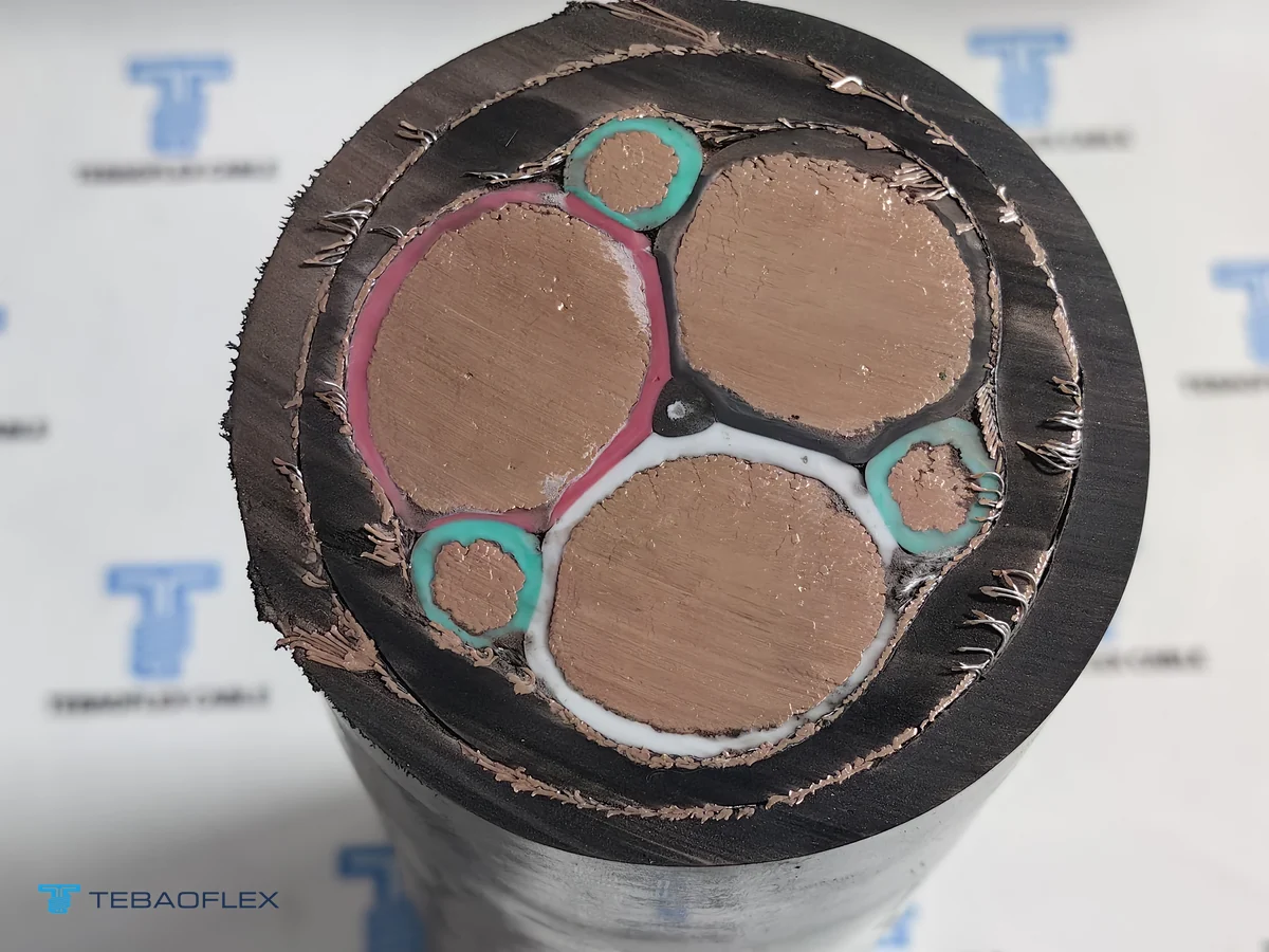
Four-core concentric 2YSLCYK-J (three phase cores plus one full-sized green-yellow protective earth) is standard up to 10–16 mm² (and wherever four-hole gland plates or local code schedules mandate a single full-size PE), whereas 3+3 symmetrical VFD cables (three phase cores plus three equal green-yellow earth cores placed in the outer valleys) are recommended from 25–35 mm² upward to suppress common-mode shaft voltage and EDM bearing fluting.
In a concentric 4-core quad lay, phase L2 sits physically farther from the single green-yellow earth core than phases L1 and L3. At 50 Hz balanced load that geometric asymmetry barely matters, but under steep PWM switching pulses it unbalances phase-to-earth mutual capacitance and induces longitudinal zero-sequence voltage along the motor rotor shaft. Splitting the protective-earth copper into three equal interstitial conductors (3 × phase + 3G split earth) places every phase equidistant from two earth cores and the concentric screen—canceling magnetic imbalance at the source.
- Fixed plant & data-center symmetrical schedule: Compare full 3+3 cross-sections from 3×16+3G2.5 mm² up to 3×240+3G50 mm² on our 2YSLCYK-JB 0.6/1 kV symmetrical VFD cable datasheet, or armoured 1.8/3 kV XLPE LSZH builds on our 2XSLCHSWAHK-J SWA armoured VFD cable page.
- Mobile mining & medium-voltage symmetrical schedules: For 2,000 V portable drives with ground-check monitoring, see our 2,000 V 3+3+GC mining VFD cable; above 2 kV, compare our 5 kV–15 kV MV mining VFD-GC cable and 3.6/6 kV & 6/10 kV flexible rubber MV VFD motor cable.
Why does 360° EMC gland termination outperform a twisted pigtail by nearly 100× at 30 MHz?
Even the finest foil-and-braid VFD cable loses its high-frequency screening if installers twist the copper braid into a side pigtail at the panel or motor box: a 120 mm pigtail introduces ~120 nH of series inductance (~22.6 Ω reactance at 30 MHz), choking high-frequency common-mode return currents and forcing them through PLC ground references and motor bearings. Bonding the braid 360 degrees inside an EMC compression gland keeps termination inductance below 1 nH.
| Screen termination method | Typical series inductance | Reactance at 10 MHz / 30 MHz | EMC & bearing-current outcome | Confirm before commissioning |
|---|---|---|---|---|
| 360° brass/SS EMC compression gland | < 1 nH coaxial contact | < 0.06 Ω / < 0.19 Ω | Full MHz common-mode return inside cable screen; IP66/IP68 entry seal | Match finished caliper OD (not just nominal OD) to gland spring/iris clamping window |
| 360° saddle clamp on cabinet EMC bar | ~1–3 nH broad-area clamp | ~0.1 Ω / ~0.4 Ω | Direct low-inductance chassis bond inside VFD switchgear cubicles | Strip 15–25 mm outer jacket window cleanly without scoring inner PE core insulation |
| 120 mm twisted braid pigtail (avoid) | ~120 nH (~1 nH/mm rule) | ~7.5 Ω / ~22.6 Ω choke | Radiates MHz noise inside drive cabinet; trips nearby RTD/encoder inputs | Replace pigtails with EMC glands or 360° earthing clips at BOTH drive and motor ends |
| Floating / one-end-only screen (avoid) | Open HF return loop | Capacitive stray return | Forces PWM common-mode current through motor shaft bearings and earth grid | Bond power VFD screen 360° at both ends; connect 3+3 green-yellow earths to PE studs |
Follow four shop-floor steps during termination on 0.6/1 kV IEC 60502-1 and DIN VDE VFD feeders:
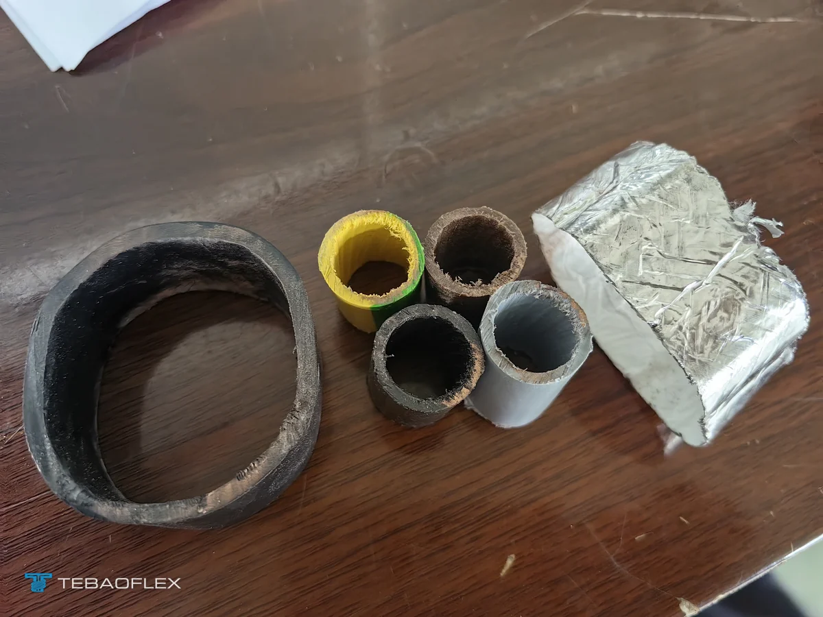
- Score outer jacket to controlled depth: Use a rotary cable stripper set 0.2 mm shallower than minimum sheath thickness so rotary blades never nick the tinned-copper braid or score soft PE primary insulation underneath.
- Fold or flare braid cleanly over the EMC gland cone/spring: Keep the aluminium-laminated foil intact up to the contact ring, trim loose polyester binder film, and seat the tinned-copper braid evenly around the full 360-degree compression spring or iris fingers.
- Keep unscreened phase tails as short as practicable: Inside both the VFD cabinet and the motor terminal box, dress unshielded L1/L2/L3 phase tails tightly (ideally ≤ 50 to 100 mm beyond the EMC clamp) and route 24 V DC / encoder / RTD cables at least 200 mm away (crossing at 90° only).
- Connect all three split-earth cores symmetrically: On 3+3 cables (2YSLCYK-JB, (N)SSHCOEU, (N)SSCHÖU-J), crimp all three green-yellow interstitial earth conductors together or onto adjacent symmetrical PE studs at both ends—never leave one split earth disconnected.
How do conduit OD, crane flexing and reel duty shape real VFD export orders?
Three 2026 TEBAOFLEX production records illustrate how finished caliper diameter, screen peel verification and jacket chemistry determine field commissioning success across fixed data centers, coastal cranes and heavy mobile drives:
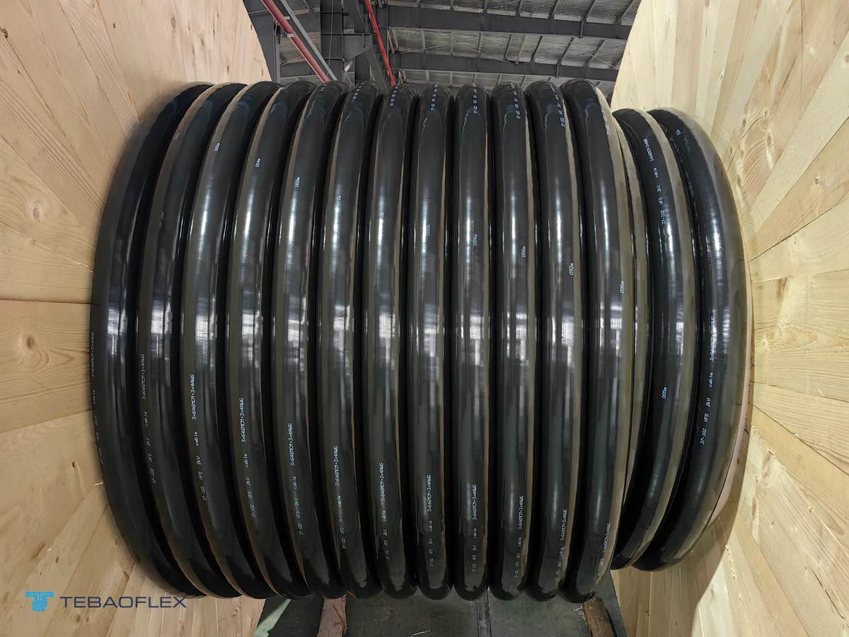
- Fixed data-center rigid conduit VFD feeder (Singapore): In our Singapore compute data center 2YSLCYK-J 0.6/1 kV 4×120 & 4×35 mm² project, chilled-water pump feeders pulled through fixed rigid tubes while matching 360-degree EMC gland clamping bores. Factory digital calipers verified 49.12 mm finished OD against the 51.9 mm nominal envelope alongside pre-shipment peel confirmation of the aluminium-foil + tinned-copper braid double screen and 4 kV AC / 5 min routine testing.
- Coastal port crane EMC auxiliary & bonding duty (Malaysia): In our Port Klang, Malaysia PUR-C-HF 0.6/1 kV 1×10 mm² screened crane cable case, extruding a halogen-free PUR inner bedding beneath an ~85 % tinned-copper wire braid and a 9.91 mm matte black PUR-HF outer jacket protected dynamic trolley circuits against Strait of Malacca salt fog, oil splash and crane VFD interference; for multi-core flat crane VFD festoons, pair with our (N)GFLCGÖU screened flat rubber cable or PUR-C-HF EMC festoon cable.
- Heavy mobile & drum-wound rubber VFD drives: Where mobile mining loaders, shaft winches or tunnel boosters wind screened feeders onto drums, multi-layer ampacity derating (0.85 for 1 layer, 0.65 for 2 layers) and Class 5 flexible copper stranding prevent core overheating and braid fatigue—verified prior to shipment under our cable factory acceptance test (FAT) protocol.
Pre-RFQ specification checklist for double-screened VFD motor cables
Confirming seven electrical and mechanical parameters upfront ensures your quotation matches inverter carrier frequency, motor bearing protection and EMC cable gland hardware without field adapter surprises.
- Installation regime: Fixed tray/conduit (2YSLCYK-J / 2YSLCYK-JB), armoured burial/rack (2XSLCHSWAHK-J), C-rail crane festoon ((N)GFLCGÖU / PUR-C-HF), or heavy trailing/reeling ((N)SSHCOEU / (N)SSCHÖU-J / 2 kV Mining VFD).
- Drive kW, voltage & carrier frequency: System voltage (0.6/1 kV, 640/1140 V, 1.8/3 kV, 2 kV or MV 3.6/6–15 kV), full-load current, PWM switching frequency (kHz) and one-way cable run length (m).
- Core symmetry & pilot cores: 4-core concentric (4G) vs 3+3 symmetrical split-earth (-JB / /3E), plus whether an insulated ground-check pilot (GC) or integrated brake/thermistor pair is needed.
- Thermal & derating environment: Maximum ambient temperature (e.g. 40–50 °C switchgear or tropics), tray grouping, or number of energized layers kept wound on a reel.
- Conduit bore & 360° EMC gland window: Rigid conduit inner diameter and exact min/max outer-sheath clamping range (mm) of your brass or stainless EMC compression glands.
- Jacket hazard profile: UV outdoor black PVC (YK), halogen-free LSZH (HK), coastal hydrolysis/oil PUR-HF, or tear-resistant yellow/black 5GM5 / CPE mining elastomer.
- Cut drum lengths & inspection records: Continuous length per wooden drum (from 50 m MOQ), routine 3.5 kV / 4 kV / 5 kV AC test certificates, and any peel-back or caliper witness photos required before dispatch.
As of November 2026, TEBAOFLEX manufactures custom fixed PE/XLPE and dynamic rubber/PUR double-screened VFD cables at our Taicang factory from a 50 m minimum order quantity (MOQ), with standard production lead times of 7 to 45 working days depending on cross-section and factory schedule. Browse our industrial and automation cables and mining and tunnelling cables catalogues, or send your inverter schedule and EMC gland bore for an engineering quotation.
Frequently asked questions
When should an inverter drive use 2YSLCYK-J or 2YSLCYK-JB instead of flexible rubber (N)SSHCOEU?
Specify 2YSLCYK-J or symmetrical 3+3 2YSLCYK-JB (0.6/1 kV, EN 50290-2-23 / DIN VDE 0276-603 reference) on fixed cable trays, data-center pump rooms and rigid conduits where low-capacitance polyethylene (PE, relative permittivity ~2.3) minimizes capacitive charging-current spikes on long runs at conductor temperatures up to +70 °C. Switch to flexible rubber (N)SSHCOEU / (N)SSCHÖU-J (DIN VDE 0250-812) or 2 kV Mining VFD cable whenever the feeder trails across rock, winds onto a reel, endures ±25°/m torsion or requires a +90 °C conductor thermal ceiling.
Why do double-screened VFD cables combine an aluminium-laminated foil with a tinned-copper wire braid?
No single metallic layer covers the entire variable-frequency drive interference spectrum efficiently. An overlapping aluminium-laminated plastic foil (applied metal side out for full optical coverage) blocks radiated electromagnetic noise above 1 MHz to 30 MHz caused by steep IGBT dV/dt switching edges, while an 80 % to 85 % optical-coverage tinned-copper wire braid in direct contact with the foil provides low DC/kilohertz transfer impedance (≤ 250 Ω/km up to 30 MHz) and carries phase-to-screen fault current.
At what motor cross-section does 3+3 symmetrical earth (2YSLCYK-JB) become preferable to 4-core concentric (2YSLCYK-J)?
In 4-core concentric 2YSLCYK-J (3 phases + 1 full-size green-yellow PE), geometric asymmetry between L1/L2/L3 and the single earth core induces modest zero-sequence voltage that is acceptable on smaller drives (typically 1.5 mm² to 16 mm², or where 4-lug gland schedules dictate equal cores). From 25–35 mm² upward on high-carrier-frequency drives with uninsulated motor bearings, 3+3 symmetrical split-earth constructions (2YSLCYK-JB, (N)SSHCOEU, (N)SSCHÖU-J) balance magnetic coupling across all three interstices to curb shaft currents and bearing fluting.
Why does twisting the VFD cable braid into a pigtail drain wire defeat a double EMC screen?
A twisted copper pigtail exhibits roughly 1 nH/mm of self-inductance. Even a short 120 mm pigtail adds ~120 nH, creating ~22.6 Ω of inductive reactance (2πfL) at 30 MHz—nearly 100 times higher impedance than a meter of double-screened VFD cable (≤ 0.25 Ω/m). High-frequency common-mode currents bypass the inductive pigtail and escape into adjacent control wiring or motor bearings; clamping the exposed braid 360 degrees inside a brass EMC compression gland eliminates that bottleneck.
What special stripping and lugging precaution applies to PE-insulated 2YSLCYK-J compared with 90 °C XLPE or EPR VFD cables?
Thermoplastic polyethylene (2Y) delivers the lowest permittivity (~2.3) among solid industrial dielectrics, but its continuous thermal ceiling is +70 °C (+160 °C short-circuit) and it softens if overheated by loose bolted lugs or torch-shrunk tubing. Torque compression lugs to calibrated values, use controlled-temperature heat guns on stress boots, or step up to cross-linked XLPE (2XSLCHSWAHK-J, +90 °C / +250 °C) or 3GI3 EPR ((N)SSHCOEU, +90 °C / +250 °C) in high-ambient switchgear cubicles.
Should a double-screened VFD cable shield be bonded at one end only or at both the inverter and motor ends?
Unlike analogue 4–20 mA instrumentation pairs (often grounded at one end to avoid 50/60 Hz ground loops), PWM motor power screens must be bonded 360 degrees at both the frequency-converter EMC plate and the AC motor terminal housing (plus intermediate metallic junction boxes) so high-frequency common-mode capacitive currents return directly inside the coaxial cable screen rather than through building steel and motor bearings.