







ANSI/ICEA S-75-381 / NEMA WC 58 (WC 23058) mining cable engineering guide
Across the five standard Type SHD-GC voltage ratings—2 kV, 5 kV, 8 kV, 15 kV and 25 kV—governed by ANSI/ICEA S-75-381 / NEMA WC 58, stepping up in voltage class increases nominal EPR phase insulation wall thickness from 70–95 mil (1.8–2.4 mm) at 2 kV to 110–120 mil (2.8–3.0 mm) at 5 kV, 150 mil (3.8 mm) at 8 kV, 210 mil (5.3 mm) at 15 kV, and 260 mil (6.6 mm) at 25 kV. At an identical copper size such as 3×4/0 AWG, 40 °C free-air ampacity barely changes (321 A to 327 A), whereas finished outside diameter grows by 30.2 mm (58.7 mm to 88.9 mm)—reshaping bend radius, coupler shells and drum capacity.
How do 2 kV, 5 kV, 8 kV, 15 kV and 25 kV SHD-GC ratings map to mine power systems?
Under ANSI/ICEA S-75-381 / NEMA WC 58 (current edition NEMA WC 23058), Type SHD-GC voltage ratings specify maximum three-phase phase-to-phase system voltage on resistance-grounded or solidly grounded mine power networks. Selecting the next higher SHD-GC class above nominal mine bus voltage ensures adequate dielectric margin during transient switching and ground-fault clearing.
Mine electrical engineers in the United States, Canada, Peru, Chile and Mexico routinely translate between North American phase-to-phase classes and IEC / DIN VDE U0/U designations (covered broadly in our medium-voltage mining cable selection guide). Use the five-tier mapping below before opening dimensional tables:
| SHD-GC voltage class | Mine system phase-to-phase bus | Closest IEC / VDE U0/U ref. | Conductor size range | Choose this when |
|---|---|---|---|---|
| SHD-GC 2 kV | 480 V, 600 V, 995 V, 1,000 V & 1,140 V AC | 0.6/1 kV & 1.8/3 kV | 6 AWG to 500 kcmil (93–536 A) | Underground continuous miners, shuttle cars, VFD pumps and 995 V longwall faces needing shielded phase fault containment |
| SHD-GC 5 kV | 2.4 kV, 3.3 kV & 4.16 kV AC | 3.6/6 kV | 6 AWG to 500 kcmil (93–536 A) | 4,160 V underground longwall power centers, blast-hole drills, crushers and medium-sized pit shovels |
| SHD-GC 8 kV | 6.0 kV, 6.6 kV, 6.9 kV & 7.2 kV AC | 6/10 kV | 4 AWG to 500 kcmil (122–536 A) | 6.6–7.2 kV open-pit electric rope shovels, hydraulic excavators and Peruvian/Andean pit ring-main skids |
| SHD-GC 15 kV | 11 kV, 12.47 kV, 13.2 kV & 13.8 kV AC | 8.7/15 kV | 2 AWG to 4/0 AWG (164–325 A) | 13.8 kV large walking draglines, pit substation jumpers, mobile pit crushers and high-head dewatering barges |
| SHD-GC 25 kV | 22 kV, 23 kV & 25 kV AC | 14/25 kV (12/20–18/30 kV) | 1 AWG to 4/0 AWG (191–327 A) | 23–25 kV ultra-class surface-mine distribution loops and primary mobile skid substation trailing feeders |
How do EPR insulation wall, CPE/TPU jacket thickness and outside diameter grow from 2 kV to 25 kV?
In TEBAOFLEX’s ANSI/ICEA S-75-381 Type SHD-GC manufacturing schedules, EPR insulation thickness rises more than threefold between 2 kV (70–95 mil / 1.8–2.4 mm) and 25 kV (260 mil / 6.6 mm), while heavy-duty CPE or TPU outer jacketing thickens from 155–265 mil up to 265–295 mil. Holding copper cross-section constant at 3×4/0 AWG, finished diameter expands from 58.7 mm (2 kV) to 88.9 mm (25 kV).
| 3×4/0 AWG configuration | Nominal EPR wall (mil / mm) | Nominal jacket (mil / mm) | Overall OD (in / mm) | Min 6×OD bend (mm) | 40 °C ampacity (A) | Confirm before ordering |
|---|---|---|---|---|---|---|
| SHD-GC 2 kV 3×4/0 + 2×1 + 1×8 AWG | 80 / 2.0 (70 mil on 6–2 AWG; 95 mil on 250–500 kcmil) | 220 / 5.6 | 2.31 / 58.7 | 352 | 321 | Confirm whether phase shielding is required over unshielded 2 kV Type G-GC |
| SHD-GC 5 kV 3×4/0 + 2×1 + 1×8 AWG | 110 / 2.8 (120 mil on 250–500 kcmil) | 235 / 6.0 | 2.50 / 63.5 | 381 | 321 | Standard 4.16 kV shovel & drill feeder; verify 5 kV coupler gland bore |
| SHD-GC 8 kV 3×4/0 + 2×1 + 1×8 AWG | 150 / 3.8 | 250 / 6.4 | 2.75 / 69.9 | 419 | 321 | Check ground-fault clearing category on 6.6 / 6.9 / 7.2 kV pit buses |
| SHD-GC 15 kV 3×4/0 + 2×1 + 1×8 AWG | 210 / 5.3 | 265 / 6.7 | 3.05 / 77.5 | 465 | 325 | Requires 15 kV stress-control cones & enlarged PN 1800–2200 export drums |
| SHD-GC 25 kV 3×4/0 + 2×1 + 1×8 AWG | 260 / 6.6 | 295 / 7.5 | 3.50 / 88.9 | 533 | 327 | Verify cable handler roller throat width ≥ 95 mm and 25 kV coupler bodies |
Full AWG-by-AWG dimension rows from 6 AWG through 500 kcmil across all five voltage classes are published on our Type SHD-GC 2 kV–25 kV shielded mining power cable product page. When sizing wooden or steel export reels for 69.9 mm to 88.9 mm medium-voltage builds inside 20GP or 40HQ containers, apply the flange-capacity formulas in our mining cable drum sizing and container loading guide.
Why do 5 kV through 25 kV SHD-GC cables require semiconductive shields and matched MV coupler kits?
Every medium-voltage Type SHD-GC phase core (and 2 kV SHD-GC where radial shielding is specified) sandwiches its 90 °C EPR dielectric between an inner semiconductive conductor shield and an outer semiconductive insulation shield overlaid with a composite tinned-copper and polyamide braid (≥ 60 % optical coverage per ICEA S-75-381). Without smooth semiconductive interfaces, air voids at stranded copper wires ionize into partial discharge above 2 kV.
Understanding what each shield layer does prevents two costly field mistakes during splicing and coupler fitting (explained step by step in our Type SHD mining cable shield construction guide):
- Inner conductor shield equalizes strand curvature: Fine rope-lay copper strands create sharp local electric-field enhancements; a semiconductive layer bonded over the conductor smooths the inner equipotential surface before entering the EPR wall.
- Clean-stripping outer insulation shield + composite copper/nylon braid: Under repeated trailing flex at 6 × OD, rigid copper tapes crack. Type SHD-GC weaves tinned copper wires with resilient polyamide (nylon) yarn over the semiconductive insulation shield so fault current drains immediately into the two bare interstitial grounding conductors (tested under our medium-voltage cable factory acceptance test protocol).
- Coupler & cold-shrink diameter matching: An 8 kV 3×4/0 AWG core over EPR measures roughly 7.6 mm thicker in insulation diameter than a 2 kV 3×4/0 AWG core. Match flameproof or quick-disconnect mine couplers (see our medium-voltage mining trailing cable coupler integration guide) to both the exact diameter over EPR insulation and finished jacket OD.
Why does 40 °C ampacity stay nearly flat across voltages—and how did a 211 A vs 321 A lookup error happen?
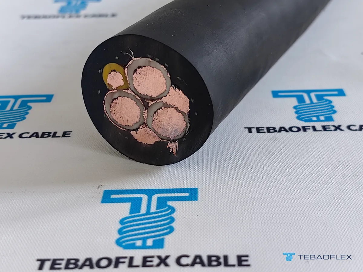
Under ICEA S-75-381 single-cable free-air tables at 90 °C conductor temperature and 40 °C ambient air, stepping a 3×4/0 AWG SHD-GC cable from 2 kV to 8 kV keeps continuous ampacity identical at 321 A (rising slightly to 325 A at 15 kV and 327 A at 25 kV), whereas misreading adjacent AWG rows—such as copying 211 A from 3×1/0 AWG—creates a 110 A specification error.
During pre-production engineering verification on our Peru 200 m SHD-GC 8 kV 3×4/0+2×1+1×8 AWG Class 6 mining cable order, commercial pro-forma text carried a transcribed figure of “211 A” alongside the 3×4/0 AWG conductor callout. Cross-checking the official ICEA S-75-381 / Product 1379 schedule immediately pinpointed the cause and prevented erroneous Certificate of Quality paperwork:
| 8 kV SHD-GC size | Overall OD (in / mm) | 40 °C free-air (A) | 1 reel layer (×0.85) | 2 reel layers (×0.65) | 3 reel layers (×0.45) | Confirm before ordering |
|---|---|---|---|---|---|---|
| SHD-GC 8 kV 3×1/0 + 2×4 + 1×8 AWG | 2.32 / 58.9 | 211 | 179 A | 137 A | 95 A | Source of the 211 A adjacent-row transcription trap; do not copy onto 4/0 AWG |
| SHD-GC 8 kV 3×2/0 + 2×3 + 1×8 AWG | 2.46 / 62.5 | 243 | 207 A | 158 A | 109 A | Common 6.6–7.2 kV medium shovel & pit pump trailing size |
| SHD-GC 8 kV 3×3/0 + 2×2 + 1×8 AWG | 2.62 / 66.5 | 279 | 237 A | 181 A | 126 A | Intermediate step when 4/0 AWG exceeds coupler entry diameter |
| SHD-GC 8 kV 3×4/0 + 2×1 + 1×8 AWG | 2.75 / 69.9 (70.94 mm measured) | 321 | 273 A | 209 A | 144 A | True 321 A free-air rating; drops near ~209 A only when wound in 2 active drum layers |
| SHD-GC 8 kV 3×250 kcmil + 2×1/0 + 1×6 AWG | 2.89 / 73.4 | 355 | 302 A | 231 A | 160 A | Ground-check steps up from 8 AWG to 6 AWG at 250 kcmil |
How do ground-check sizes, Class 6 stranding and EPR insulation colors vary across SHD-GC orders?
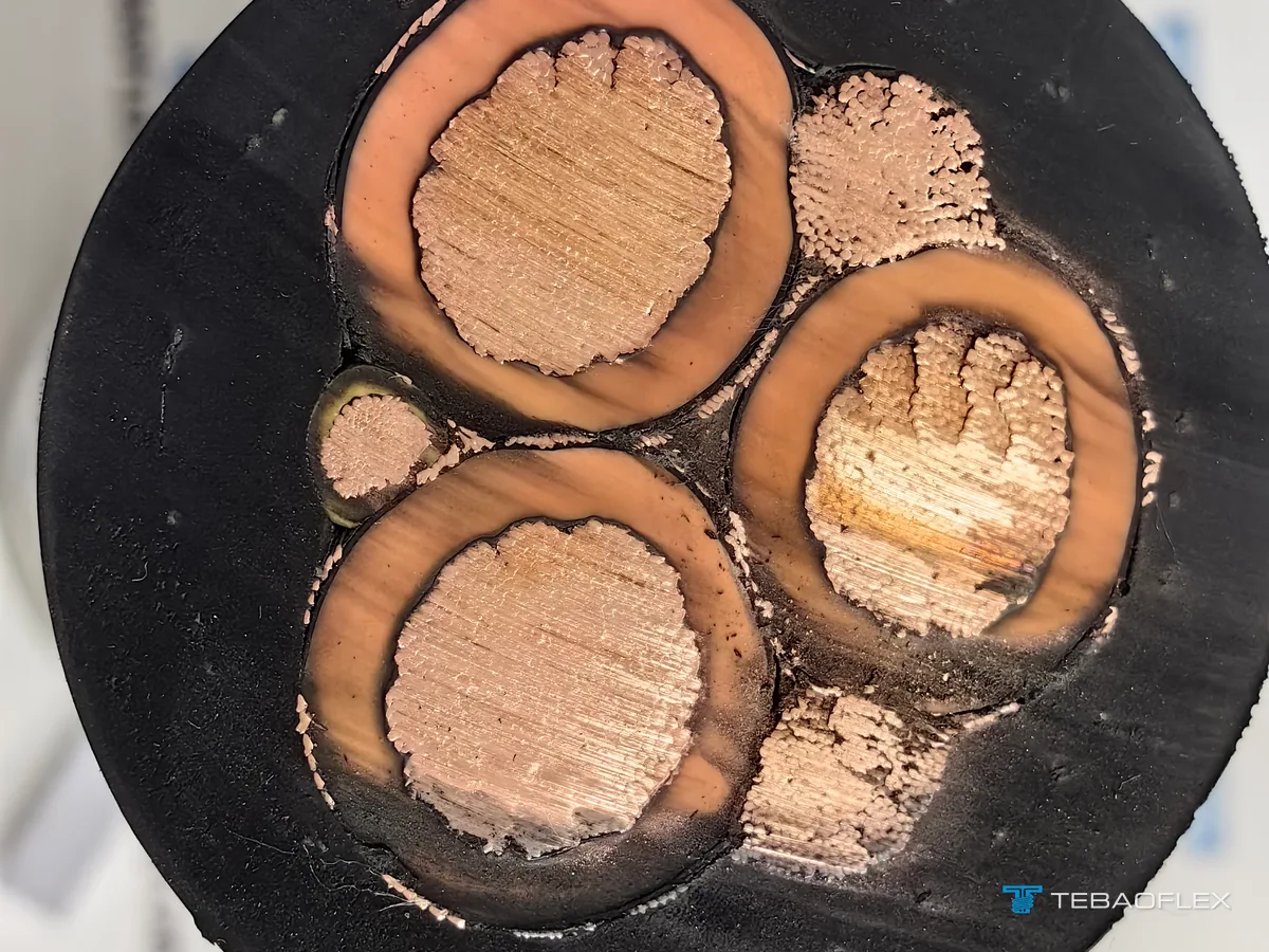
Three construction details change across SHD-GC voltage classes and custom mine specifications—and must be stated explicitly on purchase drawings rather than assumed from generic catalog headers:
- Ground-check (GC) pilot gauge steps (10 AWG → 8 AWG → 6 AWG): Under 30 CFR Part 75 Subpart I and mine ground-monitor relay practice, nuisance pilot trips mostly trace to broken pilot strands at coupler entries (covered in our mining trailing cable ground-check trip troubleshooting guide). While 2 kV 6–2 AWG builds use a 1×10 AWG yellow GC core (as on our Peru 2 kV SHD-GC 3×6+2×10+1×10 AWG orange TPU case), 2 kV 1–4/0 AWG and all 5–25 kV builds up to 4/0 AWG step up to a heavier 1×8 AWG GC core, and 250–500 kcmil feeders use 1×6 AWG.
- ASTM B172 rope-lay vs IEC 60228 Class 6 extra-flexible tinned copper: Standard North American SHD-GC uses ASTM B172 / ASTM B33 rope-lay tinned copper (for example 259 strands on 2 AWG, 323 on 2/0 AWG, 627 on 250 kcmil, 1,221 on 500 kcmil). For tight hydraulic-shovel loops or cold high-altitude Andean pits, buyers can request IEC 60228 Class 6 extra-fine tinned stranding (compared in our industrial cable conductor stranding classes guide); on our 200 m Peru 8 kV 3×4/0 AWG Class 6 build, 20 °C Kelvin bridge resistance measured 0.1736 Ω/km (173.60 mΩ/km).
- Phase EPR color vs high-visibility CPE/TPU outer jackets: At 2 kV, phase cores typically carry black/white/red EPR walls or colored identification under black CPE or high-visibility orange/yellow TPU (compared in our thermoset rubber vs TPE/TPU mining jacket guide). At 5 kV to 25 kV, buyers frequently specify pigment-compounded orange-red EPR insulation with numbered phase tapes inside black heavy-duty CPE.

When should you select Type G-GC, Type MP-GC, CSA SHD-BGC or DIN VDE (N)TMCETMPU instead of SHD-GC?
Round Type SHD-GC is the flagship North and Latin American shielded trailing cable, but four adjacent families fit specific mine circuits better depending on mobility, flat clearance or regional standards:
- 2 kV unshielded portable drills & loaders: Where 480 V or 600 V underground jumbos and loaders require ground-check monitoring without metallic phase shields, compare Type SHD-GC vs Type G-GC vs Type W and see our 2,000 V Type G-GC portable mining cable schedule.
- 2 kV low-profile shuttle cars & continuous miners: Specify our 2 kV flat 3-conductor Type SHD shielded mining cable where flat monospiral shuttle-car reels prohibit round 50 mm profiles.
- Fixed or semi-permanent 5–25 kV borehole & drift feeders: Heavy trailing stranding is unnecessary in fixed mine power distribution; switch to 5 kV–35 kV Type MP-GC EPR/CPE mine power feeder cable.
- Canadian CSA C22.2 No. 96 mines & European DIN VDE shovels: For Canadian bare-ground-check or reeling variants, review CSA Type SHD-BGC, SHD-R and SHD-SP mining cables; for metric 6/10 kV to 14/25 kV shovel and reeling equipment, see DIN VDE 0250-813 (N)TMCETMPU 6/10–14/25 kV trailing cable.
When the route transitions upstream from portable trailing shovels into fixed 5 kV to 35 kV mine substations, cable trays or direct-buried trenches rated at +105 °C, review our Type MV-105 (5 kV, 15 kV and 35 kV) EPR vs XLPE and 100% vs 133% insulation level guide.
Pre-RFQ specification checklist for 2 kV–25 kV Type SHD-GC mining cables
Include seven engineering details on your RFQ so TEBAOFLEX can confirm exact wall dimensions, coupler compatibility and drum packing before production.
- Nominal system bus & target SHD-GC class: System phase-to-phase voltage (e.g. 995 V, 4.16 kV, 6.9 kV, 13.8 kV or 23 kV), grounding method, and target SHD-GC class (2, 5, 8, 15 or 25 kV).
- Conductor AWG/kcmil & stranding flexibility: Phase + 2×ground + 1×GC gauge (e.g. 3×4/0 + 2×1 + 1×8 AWG) and standard ASTM B172 rope-lay vs extra-flexible IEC 60228 Class 6 tinned copper.
- Duty mode & active reel layers: Free-air trailing over rock benches vs motorized cable reel (state layer count, drum barrel diameter and travel speed for ampacity derating).
- Outer jacket compound & color: Heavy-duty black vulcanized CPE, two-layer aramid-reinforced CPE, or high-visibility orange/yellow TPU (with −40 °C or −50 °C cold-bend targets).
- EPR core color & sheath legend: Standard phase identification or custom orange-red EPR, plus English or Spanish metre-marked sheath print requirements.
- Coupler / termination interface & compliance scope: Coupler brand/shell bore if pre-matched, and market marking needs. Standards such as ANSI/ICEA S-75-381 and CAN/CSA C22.2 No. 96 are design and manufacturing references rather than claimed listings or MSHA approvals; confirm exact marking availability per order.
- Cut lengths & container dispatch: Continuous drum lengths (such as 200 m, 500 m or 1,000 ft), FOB/CIF port, and Certificate of Quality (COQ) routine test witness items.
As of November 2026, TEBAOFLEX manufactures custom 2 kV to 25 kV Type SHD-GC cables at our Taicang facility from a 50 m minimum order quantity (MOQ), with standard production lead times of 7 to 45 working days depending on voltage tooling and production schedule. Browse system architectures on our mining and tunneling cable solutions hub, view all regional constructions in our mining and tunneling cables catalogue, or request an engineering datasheet and quotation for your SHD-GC voltage class.
Frequently asked questions
What are the five standard voltage ratings of Type SHD-GC mining cable under ICEA S-75-381?
Under ANSI/ICEA S-75-381 / NEMA WC 58 (current designation NEMA WC 23058), round Type SHD-GC shielded portable mining power cables are manufactured in five nominal phase-to-phase voltage classes: 2,000 V (2 kV), 5,000 V (5 kV), 8,000 V (8 kV), 15,000 V (15 kV) and 25,000 V (25 kV), covering mine distribution circuits from 480 V and 995 V longwall faces up to 4.16 kV, 7.2 kV, 13.8 kV and 25 kV pit shovels, draglines and mobile substations.
How thick is the EPR phase insulation on 2 kV, 5 kV, 8 kV, 15 kV and 25 kV SHD-GC cables?
In standard ICEA S-75-381 / TEBAOFLEX Type SHD-GC schedules, nominal ethylene-propylene rubber (EPR) phase insulation thickness steps up with dielectric stress: 70 mil (1.8 mm) on 2 kV 6–2 AWG, 80 mil (2.0 mm) on 2 kV 1–4/0 AWG, and 95 mil (2.4 mm) on 2 kV 250–500 kcmil; 110 mil (2.8 mm) on 5 kV up to 4/0 AWG and 120 mil (3.0 mm) on 5 kV 250–500 kcmil; 150 mil (3.8 mm) across 8 kV; 210 mil (5.3 mm) across 15 kV; and 260 mil (6.6 mm) across 25 kV.
Does stepping up from 2 kV or 5 kV to 8 kV or 15 kV SHD-GC reduce conductor ampacity?
No. At 90 °C maximum conductor temperature and 40 °C ambient free air, single-cable Type SHD-GC ampacity stays constant or increases by 1 % to 2 % at higher voltage classes because the larger outside diameter expands convective and radiative surface area faster than the thicker EPR wall adds thermal resistance. For example, 3×4/0 AWG SHD-GC is rated 321 A at 2 kV, 5 kV and 8 kV, 325 A at 15 kV, and 327 A at 25 kV before multi-layer reel derating.
Why was 211 A flagged as an error on an 8 kV SHD-GC 3×4/0 AWG mining cable quotation?
In the 8 kV Type SHD-GC 40 °C ambient schedule, 211 A is the continuous free-air rating of 3×1/0 AWG + 2×4 AWG + 1×8 AWG (2.32 in / 58.9 mm OD), whereas 3×4/0 AWG + 2×1 AWG + 1×8 AWG (2.75 in / 69.9 mm nominal OD) is rated 321 A. Cross-reading adjacent AWG rows or mixing multi-layer reel-derated values with free-air base ratings is a common tender paperwork error that must be caught before issuing Certificates of Quality.
When should 2 kV Type SHD-GC be chosen over 2 kV Type G-GC?
Both Type G-GC and 2 kV Type SHD-GC are rated 2,000 V with two interstitial grounding conductors and one insulated ground-check core, but Type G-GC has unshielded EPR phase cores. Specify 2 kV Type SHD-GC when 995 V / 1,000 V continuous miners, shuttle cars, wet-drift feeders or VFD-driven mining motors require individual metallic phase shields over semiconductive layers to contain phase-to-ground fault currents and PWM common-mode noise.
How does ground-check conductor AWG size change across SHD-GC voltage ratings and AWG sizes?
In TEBAOFLEX’s ANSI/ICEA S-75-381 Type SHD-GC schedules, the yellow TPE-E or polypropylene insulated ground-check (GC) pilot core is 1×10 AWG on compact 2 kV cables from 6 AWG through 2 AWG, steps up to heavy-duty 1×8 AWG for mechanical pull endurance on 2 kV 1–4/0 AWG and on all 5 kV, 8 kV, 15 kV and 25 kV sizes through 4/0 AWG, and steps up to 1×6 AWG on 250 kcmil to 500 kcmil feeders.