









JIS C 3327 & crane reeling engineering guide
In Japanese cabtyre standard JIS C 3327, any 2PNCT vs 3PNCT cable comparison comes down to outer sheath reinforcement rather than finer copper stranding: 2PNCT (Grade 2) uses a single-layer chloroprene rubber sheath for lighter festoon and mobile duty, whereas 3PNCT (Grade 3) adds a synthetic-textile reinforcement layer sandwiched between an inner and outer chloroprene sheath to resist severe impact, dragging and lateral drum crush. Both grades use ethylene-propylene rubber (EPR) insulation, carry an 80 °C continuous conductor rating, and share identical flexible copper stranding at equal cross-sections.
What do the letters and leading digits in 2PNCT and 3PNCT actually mean?
Under Japanese Industrial Standard JIS C 3327 (600 V rubber cabtyre cables), 2PNCT and 3PNCT designate flexible ethylene-propylene rubber (EPR) insulated, polychloroprene (chloroprene / PCP) sheathed portable power and control cables rated 600 V AC at 80 °C maximum conductor temperature. Contrary to English-language distributor summaries that claim the leading numeral indicates finer conductor stranding, JIS C 3327 assigns 1, 2, 3 and 4 strictly to cabtyre mechanical duty and sheath wall architecture.
| Code symbol | Japanese standard term | Material or construction meaning | Confirm before ordering |
|---|---|---|---|
| 2 (in 2PNCT) | 2種 (Grade 2 cabtyre) | Single-layer heavy chloroprene outer sheath extruded over the cabled EPR cores without an internal reinforcing braid | Confirm route has no rock/ground abrasion or high-pressure multi-layer drum coiling |
| 3 (in 3PNCT) | 3種 (Grade 3 cabtyre) | Double-layer chloroprene sheath with an embedded synthetic-yarn / textile reinforcement layer vulcanised between inner and outer sheaths, plus heavier EPR insulation walls on 22 mm² and above | Verify enlarged finished outside diameter fits existing cable glands, clamps and reel grooves |
| P | EPゴム絶縁 (EP rubber) | Ethylene-propylene rubber (EPR) core insulation providing 80 °C thermal endurance, ozone resistance and cold-bend flexibility versus legacy 60 °C natural-rubber cabtyre grades (2CT / 3CT) | Check core colour code (1C black; 2C black/white; 3C black/white/red; 4C black/white/red/green; ≥5C numbered/tracer) |
| N | クロロプレンシース (Chloroprene) | Black polychloroprene (PCP / CR) elastomer sheath resisting marine salt spray, crane gearbox oil mist, sunlight weathering and flame propagation | Specify polyurethane (-U suffix) only if extreme slag or chute cut-through exceeds PCP limits |
| CT | キャブタイヤケーブル (Cabtyre) | Flexible mobile power/control cable built with fine rope-lay annealed or tinned annealed copper conductors for dynamic flexing | Specify bare versus tinned annealed copper (TA) for coastal container terminals and humid ports |
Because JIS C 3327 replaced older natural-rubber 60 °C cabtyre cables (1CT, 2CT, 3CT) with 80 °C EPR-insulated PNCT designs, standard 600 V 2PNCT achieves roughly 25 % to 35 % higher free-air current capacity (per JCS 0168-1 at 30 °C ambient) at a smaller outside diameter than legacy natural-rubber cabtyre cables of the same cross-section. For standard 600 V trolley, hoist and mobile machinery power or control runs from 0.75 mm² to 250 mm², review our 600 V 2PNCT flexible rubber cable specifications.
How do 2PNCT and 3PNCT compare at the same conductor size?
Under JIS C 3327 and JCS crane schedules at identical voltage (600 V) and copper cross-section, CAR-2PNCT and CAR-3PNCT reeling constructions use the exact same conductor stranding and have the same 20 °C maximum DC resistance, while 3PNCT increases EPR insulation wall thickness, adds a 0.5 to 1.0 mm textile reinforcement ply, and thickens total chloroprene sheathing. As a result, 2PNCT is 14 % to 18 % lighter and bends tighter, whereas 3PNCT withstands higher radial crush and tear loads.
Inspecting side-by-side reeling data from our 600 V to 1 kV PNCT round and flat reeling cable schedules makes the mechanical trade-off explicit across common crane feeder sizes:
| Model and configuration | Copper stranding (wires/mm) | EPR wall / yarn / PCP sheath (mm) | Approx. OD or H×W (mm) | Approx. mass (kg/km) | Max. 20 °C DC R (Ω/km) | Min. bend radius (mm) | Choose this when |
|---|---|---|---|---|---|---|---|
| CAR-2PNCT 3×22 mm² (600 V) | 7/20/0.45 | 1.2 / none / 2.7 | 26 mm | 1,180 | 0.919 | 160 | Compact level-wind or spring reels with clean guideways and tight sheave diameters |
| CAR-3PNCT 3×22 mm² (600 V) | 7/20/0.45 | 1.6 / 1.0 / 3.7 | 31 mm | 1,470 | 0.919 | 190 | Yard gantry reels or trailing loops exposed to tyre run-over, gravel abrasion or side impact |
| CAR-2PNCT 3×38 mm² (600 V) | 7/34/0.45 | 1.2 / none / 3.0 | 31 mm | 1,790 | 0.541 | 190 | Standard 600 V bridge/gantry crane travel feeds needing lower suspended cable weight |
| CAR-3PNCT 3×38 mm² (600 V) | 7/34/0.45 | 1.6 / 1.0 / 4.0 | 36 mm | 2,150 | 0.541 | 220 | Heavy-duty reeling drums or slag/bulk-yard walkways where single-sheath jackets split |
| CAR-2PNCT 3×60 mm² (600 V) | 19/20/0.45 | 1.5 / none / 3.4 | 38 mm | 2,790 | 0.339 | 230 | High-current LV crane hoists and trolleys where gland entry is capped below 40 mm |
| CAR-3PNCT 3×60 mm² (600 V) | 19/20/0.45 | 2.1 / 1.0 / 4.5 | 45 mm | 3,330 | 0.339 | 270 | Multi-layer cylindrical drums and rugged transfer cars with ≥ 46 mm gland clearance |
| H-2PNCT 3×38 mm² flat (600 V) | 7/34/0.45TA | 1.2 / none / 2.8 | 17.5 × 41 mm | 1,710 | 0.525 | 210 | Overhead C-track and I-beam festoon trolleys needing compact stack height |
| H-3PNCT 3×38 mm² flat (600 V) | 7/34/0.45 | 1.6 / 1.0 / 3.8 | 22 × 55 mm | 2,290 | 0.525 | 270 | Heavy outdoor flat reeling drums or high-wind coastal gantry loops requiring reinforced jacket walls |
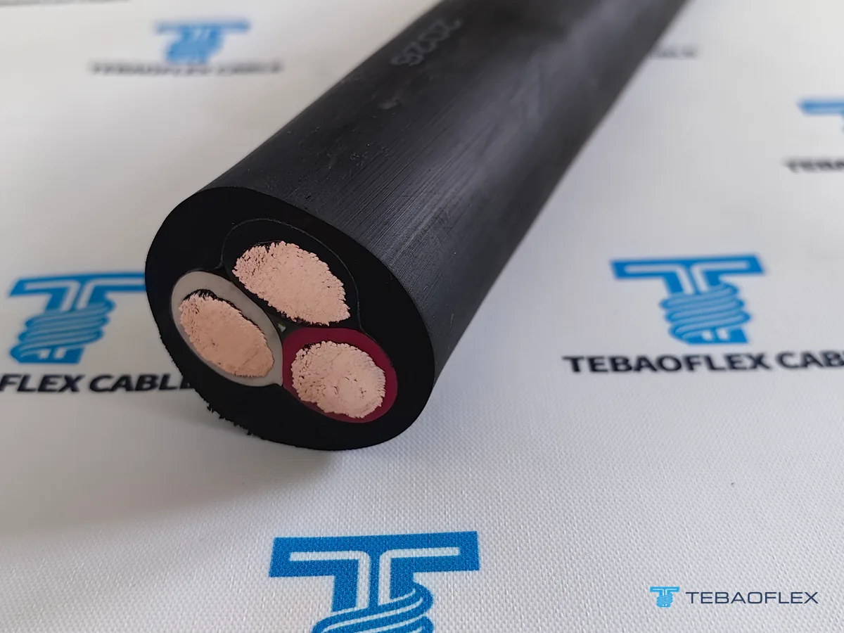

How do crane reeling, torsion and flat festoon suffixes (-B, H-, F-, -SB, -T, RE) change the cable?
Base JIS C 3327 2PNCT and 3PNCT cables are general cabtyre constructions; Japanese crane, steelworks and port OEMs add prefix or suffix codes under JCS and manufacturer standards to adapt core geometry, tensile members, EMI shielding and anti-torsion sliding wraps to specific crane motions. Ordering bare 2PNCT in place of a suffixed crane variant is a primary cause of premature corkscrewing or control-pair noise.
| Designation family | Internal structural modification | Rated mechanical / electrical limit | Choose this when |
|---|---|---|---|
| 2PNCT-B / RE-2PNCT / RE-3PNCT | Open-weave synthetic anti-twist braid (-B) or stainless-steel strand reinforcement on ≤ 8 mm² cores (RE-) | 600 V; 3,000 V / 1 min AC test; suppresses axial twist on horizontal drums | Horizontal gantry travel drums and mobile machines—see how anti-torsion braids prevent reeling corkscrew failure |
| 2PNCT-H / 2PNCT-H-U (multi-core) | Tinned copper + stainless-steel hybrid conductors; unit-assembled control cores (-H-U) up to 42×3.5 mm² | 600 V, −15 to +80 °C; tensile rating 1.7 kN (3×38) up to 5.8 kN (10×3.5) | High-cycle container crane festoon loops—compare our festoon power, control and PG cable solutions |
| H-2PNCT / 2PNCT-F / F-3PNCT (flat) | Parallel single-row (1+1+1+1) core lay-up in a flat chloroprene profile; F-3PNCT / H-3PNCT add Grade 3 reinforcement | 600 V; F-3PNCT tensile rating 1.9 kN (3×22) up to 22.0 kN (3×250 mm²) | C-track / I-beam festoon trolleys and narrow monospiral reels where round cables stack too high |
| 2PNCT-SB / 2PNCT-BS / CAR-2PNCT-SX | Overall tinned-copper braid (-SB), pair-shielded instrumentation (-BS), or conductive-rubber + drain shield (-SX) | 600 V, min. 400 MΩ·km insulation resistance at 20 °C on 3.5 mm² control cores | VFD hoist motor leads, pulse-generator (PG) encoders and crane PLC signals exposed to IGBT switching noise |
| 2PNCT-T / 3PNCT-T / TOR-2PNCT | Sliding core separator wraps and torsion-compensated pitch; 3PNCT-T adds cloth-reinforced double sheath | 600 V, bend radius ≥ 7.5 × OD, permissible sidewall pressure ≤ 4,900 N/m | Rotating crane spreaders, slewing bridges, stacker-reclaimer booms and wind/turntable loops—see 600 V PNCT torsion cables |
| RE(V)-2PNCT-RF (vertical reel) | 7, 10 or 13 fine tinned-copper cores (3.5 or 5.5 mm²) balanced for vertical gravity-fed / driven spreader reels | 600 V, 80 °C, 3,000 V / 1 min test, lateral drum pressure ≤ 4.9 kN/m | Vertical container spreader reels—see 600 V RE(V)-2PNCT-RF vertical reeling cable |
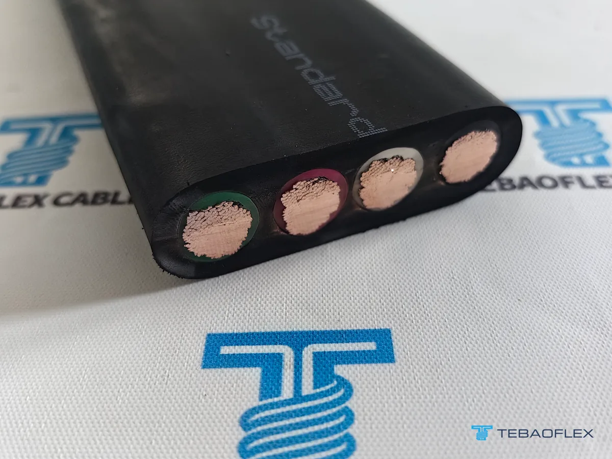
Why medium-voltage 3.3 kV and 6.6 kV port crane reels use the 3PNCT reinforced architecture
Above 600 V, Japanese port crane and bulk-yard power reels move from JIS C 3327 to JCS 3416 and Japan’s Technical Standards for Electrical Equipment, adopting the Grade 3 reinforced double-sheath 3PNCT platform across 3.3 kV and 6.6 kV (plus IEC-tier 3.6/6 kV and 6/10 kV PNCT-R / PNCT-RF export builds). Each phase core adds an inner semi-conductive layer, 3.0 to 5.0 mm ozone-resistant EPR wall, outer semi-conductive layer, and copper or hybrid screen braid.
When specifying replacement cables on ship-to-shore (STS) quayside cranes, rail-mounted gantries (RMGs) or ship unloaders from our 3.3–6.6 kV 3PNCT, H-3PNCT and FG-H-3PNCT crane reeling cable range (or round electro-optical FC-PNCT composite fibre-optic reeling cables), separate the four medium-voltage sub-families by drum geometry and test voltage:
| MV PNCT sub-family | Rated voltage & AC withstand test | Representative 3×38 / 3×35 mm² dimensions & mass | Mechanical & optical parameters | Choose this when |
|---|---|---|---|---|
| 6.6 kV 3PNCT-B & G-3PNCT-B (round) | 6.6 kV AC; 17,000 V for 10 min | 6.6 kV 3PNCT-B 3×38: 59.0 mm std OD (62.0 mm max), 4,620 kg/km | 3.3 kN tensile limit on 3×38 (7.0 kN on 3×80+1×38+14 GI); lateral crush ≤ 4.9 kN/m | Cylindrical multi-wrap crane or reclaimer drums with multi-plane deflection sheaves |
| 3.3 kV & 6.6 kV H-3PNCT (flat power) | 3.3 kV (9,000 V / 10 min) or 6.6 kV (17,000 V / 10 min) | 3.3 kV 3×38: 29 × 65 mm, 3,190 kg/km; 6.6 kV 3×38: 34 × 78 mm, 4,200 kg/km | 3.0 mm (3.3 kV) or 5.0 mm (6.6 kV) EPR wall; 1.0 mm reinforcement; min. bend R 470 / 550 mm | Narrow monospiral STS and RMG reels without integrated optical fibres |
| 3.3 / 6.6 kV FG-H-3PNCT & FG-3PNCT (flat + FO) | 3.3 kV (9,000 V / 10 min) or 6.6 kV (17,000 V / 10 min) | 6.6 kV FG-H-3PNCT 3×38+1×22+6FO: 35 × 103 mm, 5,660 kg/km, bend R 560 mm | 6–14 GI 50/125 or 62.5/125 µm fibres (≤ 4.0 dB/km at 0.85 µm); optional control cores in FG-H-3PNCT-C | Automated STS/RMG monospiral reels combining MV power, earth core and crane telemetry |
| 3.6/6 kV & 6/10 kV PNCT-R / PNCT-RF | 3.6/6 kV (9,000 V / 5 min) or 6/10 kV (17,000 V / 5 min) | 6/10 kV PNCT-R 3×35: 56.0 mm OD; PNCT-RF 3×35: 31.5 × 72.5 mm, 3,900 kg/km | Fine 0.26 mm max wire diameter on 16–120 mm² IEC conductor sizes; ≥ 400–500 MΩ·km at 20 °C | Terminals running IEC 3.6/6 or 6/10 kV switchgear on Japanese-pattern crane reels |
For a real port crane replacement showing why an initial 6.6 kV 3PNCT 3×50 mm² inquiry required flat F-3PNCT to fit a single-slot radial monospiral drum and three-roller quay guide, see our Hai Phong Port 6.6 kV F-3PNCT 3×50 mm² crane reeling cable case.
Can DIN VDE (N)SHTÖU, NGFLGÖU or (N)TSCGEWÖU replace JIS 2PNCT and 3PNCT on existing cranes?
European DIN VDE 0250 crane cables can replace Japanese JIS/JCS PNCT cables on port cranes only as engineered functional alternatives—never as blind catalogue swaps—because nominal conductor sizes, voltage designations, continuous conductor temperature ratings (90 °C DIN VDE versus 80 °C JIS/JCS) and outer dimensions differ. Every cross-standard replacement must pass a conductor resistance, ampacity and mechanical slot-width check first.
First, reconcile conductor cross-sections: Japanese crane schedules use 8, 14, 22, 30, 38, 50, 60, 80, 100 and 150 mm², whereas IEC 60228 and DIN VDE 0250 use 10, 16, 25, 35, 50, 70, 95, 120 and 150 mm². Stepping down from 38 mm² JIS (0.525 to 0.541 Ω/km at 20 °C) to 35 mm² IEC Class 5 tinned copper (0.565 Ω/km) raises DC resistance by roughly 4 % to 7 %; long gantry travel runs with tight voltage-drop budgets often step up to 50 mm² IEC (0.393 Ω/km) provided the drum groove or festoon clamp accepts the wider profile. For VDE code letter rules, see how to read DIN VDE cable designations.
| Existing Japanese cable | DIN VDE 0250 functional alternative | Key standard & rating differences | Confirm before ordering |
|---|---|---|---|
| 600 V H-2PNCT / 2PNCT-F (flat festoon) | NGFLGÖU / NGFLGOEU-J 300/500 V & 0.6/1 kV flat festoon cable | 0.6/1 kV DIN VDE 0250-809 EPR/PCP flat build rated 90 °C conductor vs 600 V / 80 °C JIS | Check carrier clamp window width × height—see our Vietnam 66 × 22 mm NGFLGOEU-J crane tender case |
| 600 V 2PNCT-B / CAR-2PNCT / CAR-3PNCT (round LV reel) | (N)SHTÖU-J / NSHTOEU-J 0.6/1 kV anti-torsion reeling cable | DIN VDE 0250-814 0.6/1 kV 3GI3 EPR + embedded aramid/synthetic braid + 5GM3/5GM5 PCP sheath (90 °C) | Verify maximum cable OD against level-wind guide rollers, stuffing glands and split-earth (3+3) vs 4-core lugging |
| 3.3 / 6.6 kV 3PNCT-B & G-3PNCT-B (round MV reel) | (N)TSCGEWÖU 3.6/6 kV to 18/30 kV round crane reeling cable | DIN VDE 0250-813 3.6/6 or 6/10 kV screened EPR + anti-torsion double sheath; 5 min VDE AC test vs 10 min JCS test | Check monospiral or Lebus drum groove pitch and OD window—see our 6/10 kV ship-unloader reeling diameter case |
| 3.3 / 6.6 kV H-3PNCT & FG-H-3PNCT (flat MV + FO reel) | (N)TSFLCGEWÖU flat MV reeling cable or (N)TSFLCGEWÖU-FO flat optical reeling cable | 3.6/6 to 12/20 kV flat screened EPR/PCP (or +6–24 GI/SM fibres); higher voltage headroom for 11–15 kV crane retrofits | Confirm exact slot width inside monospiral drum cheeks and match GI 50/125 vs 62.5/125 vs OS2 optical transceivers |
Four field specification mistakes we see on port crane PNCT replacement enquiries
Across Southeast Asian and East Asian container terminal maintenance enquiries, four recurring specification errors cause delivery delays, clamp refits or premature sheath failure when replacing Japanese crane cables. Catching these four mismatches during technical clarification avoids ordering the wrong profile or oversize cross-section:
- Upgrading 2PNCT to 3PNCT expecting tighter bending on small festoon saddles: Maintenance buyers frequently assume 3PNCT uses finer copper wires than 2PNCT. In reality, copper stranding is identical (for example 7/34/0.45 on 38 mm²), while the added 1.0 mm reinforcement layer and thicker sheath increase CAR-3PNCT 3×38 mm² diameter by 5 mm (31 mm to 36 mm) and raise minimum bend radius from 190 mm to 220 mm. Where tighter bend radius or lighter trolley load is needed, stay in single-sheath 2PNCT or flat H-2PNCT.
- Accepting a 2+2 stacked core layout when a festoon system requires single-row 1+1+1+1 flat 2PNCT: On 4-core crane travel loops (such as 3×38 mm² plus earth), a bundled 2×2 core arrangement behaves mechanically like a square cable, doubling bending thickness over trolley saddles and jamming flat clamp bars. Specify single-row parallel core alignment (H-2PNCT, 2PNCT-F, H-3PNCT or F-3PNCT) and confirm nominal thickness × width in millimetres.
- Sizing a single crane reeling feeder from total installed motor kW instead of simultaneous demand: Port cranes never run main hoist full-load lift, trolley travel, boom hoist and gantry travel at nameplate peak simultaneously (hoisting and gantry travel are often electrically interlocked). Summing every motor nameplate kW inflates a 6.6 kV 3PNCT feeder from 3×38 or 3×50 mm² up to an oversize cross-section that will not fit the existing monospiral drum slot—apply simultaneous duty-factor sizing as detailed in our reeling cable replacement and simultaneous-load identification guide.
- Measuring a swollen 10-to-15-year-old chloroprene jacket with calipers and treating it as nominal OD: After a decade of grease, hydraulic oil mist, solar heat and flexing tension, aged rubber reeling jackets routinely swell by 4 to 6 mm. Ordering a new 3PNCT or VDE cable to match the swollen caliper reading risks jamming tighter unworn sections of the reel guide—verify true conductor stranding and original reel drawing groove width first, alongside the mechanical checks in our reeling cable drum, speed and tension selection guide.
What to specify when ordering 2PNCT, 3PNCT or cross-standard crane replacement cables
Whether you want TEBAOFLEX to manufacture direct to Japanese JIS C 3327 / JCS reference dimensions (2PNCT, 2PNCT-B, H-2PNCT, CAR-3PNCT, 3.3/6.6 kV H-3PNCT, F-3PNCT or FG-H-3PNCT) or engineer a slot-matched DIN VDE 0250 alternative within our port and container crane cable solutions and port and festoon cable catalogue, include five project parameters in your enquiry:
- Full designation and voltage class: Exact sheath legend (for example 600 V 2PNCT-B 3×60 mm², 600 V H-2PNCT 4×38 mm², or 6.6 kV FG-H-3PNCT 3×50+1×30+6FO) plus system voltage and frequency.
- Core geometry and optical/control count: Round versus single-row flat (1+1+1+1) profile, earth-core arrangement, control core count, and graded-index (GI 50/125 or 62.5/125 µm) versus single-mode fibre specification.
- Mechanical envelope and hardware window: Maximum allowable outside diameter or flat thickness × width (mm) at monospiral drum cheeks, roller guides, festoon clamps and terminal glands.
- Motion duty and environment: Festoon trolley travel versus horizontal/vertical driven reel, minimum drum barrel and sheave diameters, travel speed (m/min), travel length, and ambient port temperature range.
- Inspection and delivery length: Individual cut drum lengths, continuous-length tolerances, and routine factory test records required (20 °C conductor DC resistance, insulation resistance, 1-minute / 5-minute / 10-minute AC withstand voltage, and OTDR fibre attenuation where applicable).
As of November 2026, TEBAOFLEX supplies both standard-reference and custom-engineered crane rubber cables from a 50 m minimum order quantity across standard and customised constructions alike, with manufacturing lead times of 7 to 45 working days depending on cable structure, stock position and project testing scope. JIS Mark, PSE, UL and CSA product marks are not claimed on TEBAOFLEX PNCT constructions; each drum is verified against the agreed order datasheet before export packing. Send your 2PNCT, 3PNCT or crane drum drawing parameters for engineering review.
Frequently asked questions
Does 3PNCT have finer copper stranding than 2PNCT?
No. Under Japanese standard JIS C 3327 and JCS crane cable schedules, 2PNCT and 3PNCT use identical flexible copper stranding at the same conductor cross-section—for example, 7/34/0.45 mm wires (9.1 mm conductor diameter, 0.541 Ω/km maximum DC resistance at 20 °C) on both CAR-2PNCT 3×38 mm² and CAR-3PNCT 3×38 mm². The digit 3 denotes a textile-reinforced double chloroprene sheath, which actually makes 3PNCT thicker and slightly stiffer in bend radius than 2PNCT.
What do the letters P, N and CT stand for in 2PNCT and 3PNCT?
In JIS C 3327 rubber cabtyre nomenclature, P stands for ethylene-propylene rubber (EP or EPR) conductor insulation, N stands for chloroprene rubber (polychloroprene, PCP, historically Neoprene) outer sheathing, and CT stands for cabtyre flexible portable cable. The leading numeral 2 or 3 specifies Grade 2 single-layer chloroprene sheathing versus Grade 3 reinforced double-layer chloroprene sheathing.
When should a port crane use 2PNCT instead of 3PNCT?
Under JIS C 3327 and JCS crane schedules, select 600 V 2PNCT (or flat H-2PNCT / 2PNCT-F) when the cable hangs freely in overhead C-track or I-beam festoon loops without ground dragging, severe impact, or high-tension multi-layer drum coiling. At 3×38 mm², single-sheath CAR-2PNCT cuts outside diameter from 36 mm to 31 mm, lowers cable mass from 2,150 kg/km to 1,790 kg/km, and tightens minimum bending radius from 220 mm to 190 mm compared with CAR-3PNCT.
Why are 3.3 kV and 6.6 kV Japanese STS and RMG crane reeling cables always 3PNCT variants?
Medium-voltage ship-to-shore (STS) and rail-mounted gantry (RMG) main power reels combine high linear travel speeds, multi-ton suspended weight, and lateral drum sidewall pressures up to 4.9 kN/m. Extending JIS C 3327 Grade 3 principles into JCS 3416 crane constructions, 3PNCT-B, H-3PNCT, F-3PNCT and optical-composite FG-H-3PNCT pair the reinforced double chloroprene sheath with screened EPR phase cores tested at 9,000 V (3.3 kV) or 17,000 V (6.6 kV) AC for 10 minutes.
Can DIN VDE (N)SHTÖU or (N)TSCGEWÖU replace JIS 2PNCT and 3PNCT on an existing crane?
Yes, provided three physical interfaces are checked before ordering: conductor size step-up (Japanese metric sizes 14, 22, 30, 38, 60 and 80 mm² must map to IEC 60228 sizes 16, 25, 35, 50, 70 and 95 mm² for ampacity and voltage drop), finished outside diameter or flat width-by-thickness fit inside existing monospiral drum grooves and gland seals, and core colour or earth-conductor arrangement at terminal lugs.
What is the difference between flat H-2PNCT / H-3PNCT and bundled 2+2 core crane cables?
True flat crane cables such as H-2PNCT, 2PNCT-F, H-3PNCT and F-3PNCT align all three or four cores side by side in one horizontal row (1+1+1+1 geometry) so every conductor sits near the neutral bending plane over festoon saddles or narrow monospiral reels. A 2+2 stacked core layout doubles cable thickness, increases minimum bending radius, and fails to seat inside standard flat festoon carrier clamps.