


Cable screen construction
A spiral shield, also called a serve shield, lays tinned copper wires side by side in one helical direction around the core; a braided shield interweaves groups of wires in two directions. Tinned copper can be used for either, so the material name on a datasheet does not tell you which construction you are getting. This guide compares the two layouts on TEBAOFLEX cable samples cut open in the factory, explains what braid coverage means and does not mean, and lists what to write into an enquiry for a screened cable.
Spiral shield vs braided shield at a glance
Most of what the internet has to say about serve versus braid was written for guitar leads and microphone cables, where the worst case is a hum in the second chorus. The same two constructions sit inside medium-voltage switchgear tails, VFD motor cables and mining trailing cables, where the worst case is a tripped drive or a screen that opens up on a cutter boom. The physics is identical; the consequences and the specifications are not. The table below is the industrial version.
| Question | Spiral / serve shield | Braided shield |
|---|---|---|
| How the wires lie | Side by side, one helical direction, no interweaving | Groups of wires (carriers) interwoven over and under |
| Flexing and small bend radius | Follows tight bends; wires slide, they do not lock | Stiffer; the weave resists bending and adds tensile strength |
| Coverage under movement | Can open into gaps when stretched, kinked or bent repeatedly | Coverage stays consistent as the cable flexes |
| Frequency behaviour | A helix behaves like a coil; transfer impedance rises with frequency | Interweaving gives many cross paths; holds up to higher frequencies |
| Termination | Unwind, twist and crimp or solder | Comb out, pigtail or use a braid-clamp gland |
| Production | Faster, fewer wire ends | Slower, more wire; cost rises with coverage |
| Typical industrial home | Concentric wire screens and protective wires on flexible medium-voltage single cores | EMC screens on VFD and festoon cables, composite copper/textile screens on mining trailing cables |
Neither is the better shield in the abstract. One is the better shield for a cable that must bend a thousand times around a small radius; the other is the better shield for a cable that must hold its coverage and shunt high-frequency noise for a decade. Everything below is about telling which cable you have.
What is a spiral shield, or serve shield?
A spiral shield, also called a serve shield, is a layer of copper wires laid side by side in one helical direction around a cable core, without interweaving. Because every wire runs the same way, the layer flexes freely and terminates quickly, but it can part when the cable is stretched or kinked, and the helix behaves like a coil.
The sample below is a TEBAOFLEX single-core cable cut back in the factory: conductor, insulation, a black semiconductive layer, then the tinned copper wires served over it, then the red sheath. Look at the wires and you will see what defines the construction. They lie parallel, each at the same lay angle, and none passes over or under a neighbour. That is a serve. On the factory floor the operation is called serving or, in some Chinese plants, “vertical winding”; the machine that does it is a serving head, not a braider.
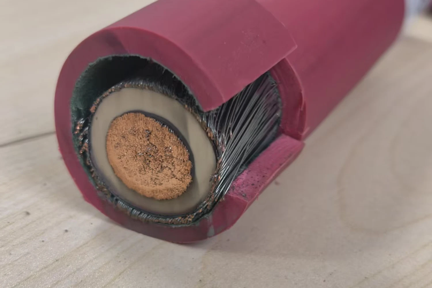
Two things follow from the geometry. First, a served layer has no mechanical lock between wires, so it bends around a small radius without work-hardening the copper the way a locked weave does; it is the natural choice where a screened single core must be trained tightly inside switchgear or coiled on a machine. Second, the same freedom means that if the cable is pulled hard or kinked, the wires can slide apart and leave a gap in the screen. A reverse spiral, two served layers in opposite directions with no interweaving, closes most of the gaps and is sometimes mistaken for a braid in a photograph; the difference is that the layers sit on top of each other rather than passing through each other.
Electrically, a helix of wires is a coil. At power frequency and the lower harmonics that is irrelevant, which is why served copper wire screens are standard practice on medium-voltage power cables; at the megahertz edges produced by a fast-switching drive the coil’s inductance appears in the screen’s transfer impedance, and a serve lets more of that energy through than a braid of the same coverage. That is the physical basis for the rule of thumb that a serve is a low-frequency screen.
What is a braided shield?
A braided shield is a tubular weave of copper wires in which groups of wires, called carriers, cross over and under each other in two opposing helical directions. The interweaving locks the layer together, so coverage stays stable when the cable flexes and the braid carries mechanical load, at the cost of stiffness, slower production and harder termination.
The second factory sample is the same idea in braid. Under the red sheath and a green textile serving, the tinned copper wires cross in the diamond pattern that every electrician recognises: one carrier passes over the next and under the one after, in both directions at once. Nothing about the copper itself is different from the serve; the machine and the geometry are.
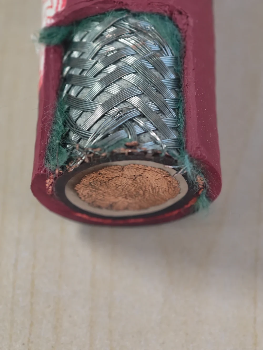
The weave is what buys the braid its reputation. Because each carrier is held by the ones crossing it, the layer keeps its coverage when the cable is bent, twisted or pulled, and it contributes tensile and crush strength that a serve does not. Because current can cross from wire to wire at every intersection, the braid does not behave as a single coil, and its transfer impedance stays low to far higher frequencies than a serve of the same optical coverage. The price is paid three times: a braider is slower than a serving head, a braid uses more copper for the same coverage, and the installer has to comb the weave out to make a pigtail or fit a gland that clamps it.
Spiral shield vs braided shield: what actually differs?
The two constructions differ in how the wires are held. A serve leaves the wires free, so it bends better, terminates faster and costs less, but can open under strain and lets high-frequency noise through. A braid locks the wires, so it holds coverage, adds strength and screens to higher frequencies, but is stiffer, slower and harder to terminate.
| Property | Spiral / serve | Braid | What it means on site |
|---|---|---|---|
| Wire arrangement | Parallel wires, one lay direction | Carriers interwoven in two directions | Confirm from a cut sample or the construction drawing, never from the word “screened” |
| Minimum bend radius and flex life | Better: wires slide, copper is not locked | Poorer: the weave resists and work-hardens with repeated tight bends | Reeling, cutter booms and switchgear tails favour the serve or a composite braid |
| Coverage stability | Gaps can open under tension or kinking | Stays consistent when flexed | Cables that are dragged or pulled favour the braid |
| Screening at high frequency | Falls off as frequency rises (coil effect) | Maintained to higher frequencies | Drive output cables favour the braid; power-frequency screens do not need it |
| Mechanical contribution | None worth counting | Adds tensile and crush resistance | Braids double as tensile members on some cutter and reeling cables |
| Termination | Unwind and twist into a tail | Comb out, pigtail or clamp in a 360° gland | EMC glands assume a braid; check the gland range against the screen diameter |
| Cost and speed | Lower, faster | Higher, slower; both rise with coverage | Coverage above about 90 % is bought, not assumed |
| Verification | Optical coverage from the construction; transfer impedance to IEC 62153-4-3 and screening attenuation to IEC 62153-4-4 where EMC performance is specified | Ask for the figure that matches the requirement, not a photograph | |
| Duty | Specify | Choose this when |
|---|---|---|
| Flexible single-core medium-voltage links inside switchgear or on machines | Served (spiral) tinned copper wires over the insulation screen | The core must be trained around a small radius and the screen carries power-frequency charging and fault current: (N)TMCGC11Y screened MV switchgear cable |
| Converter-to-motor and festoon circuits with EMC requirements | Overall tinned copper braid, coverage stated | The screen must stay closed under movement and work at drive switching frequencies: (N)SSHCÖU EMC screened VFD cable, (N)GRDGCGÖU-J screened festoon cable |
| Mining trailing cables with individually screened cores | Composite braid of tinned copper and textile yarn | Each core needs a screen that survives dragging and flexing: Type 209 screened mining cable, SHD-GC 2–25 kV mining cable |
| Cutter and shearer cables bent around the smallest radii | Spiral of copper and steel wires for the concentric earth; braid only where pull, not bending, governs | Bend radius rules over tensile load: (N)SSHCGEÖU low-tensile cutter cable |
| Fixed medium-voltage feeders | Concentric copper wire screen (helical) or copper tape, per the construction standard | Installed once; the screen is sized for fault current, not for EMC |
If a quotation says only “screened” or “shielded”, the word has told you nothing about which row you are in. Ask for the construction drawing, or send the duty to the engineering team and let them name the construction.
What does braid coverage mean?
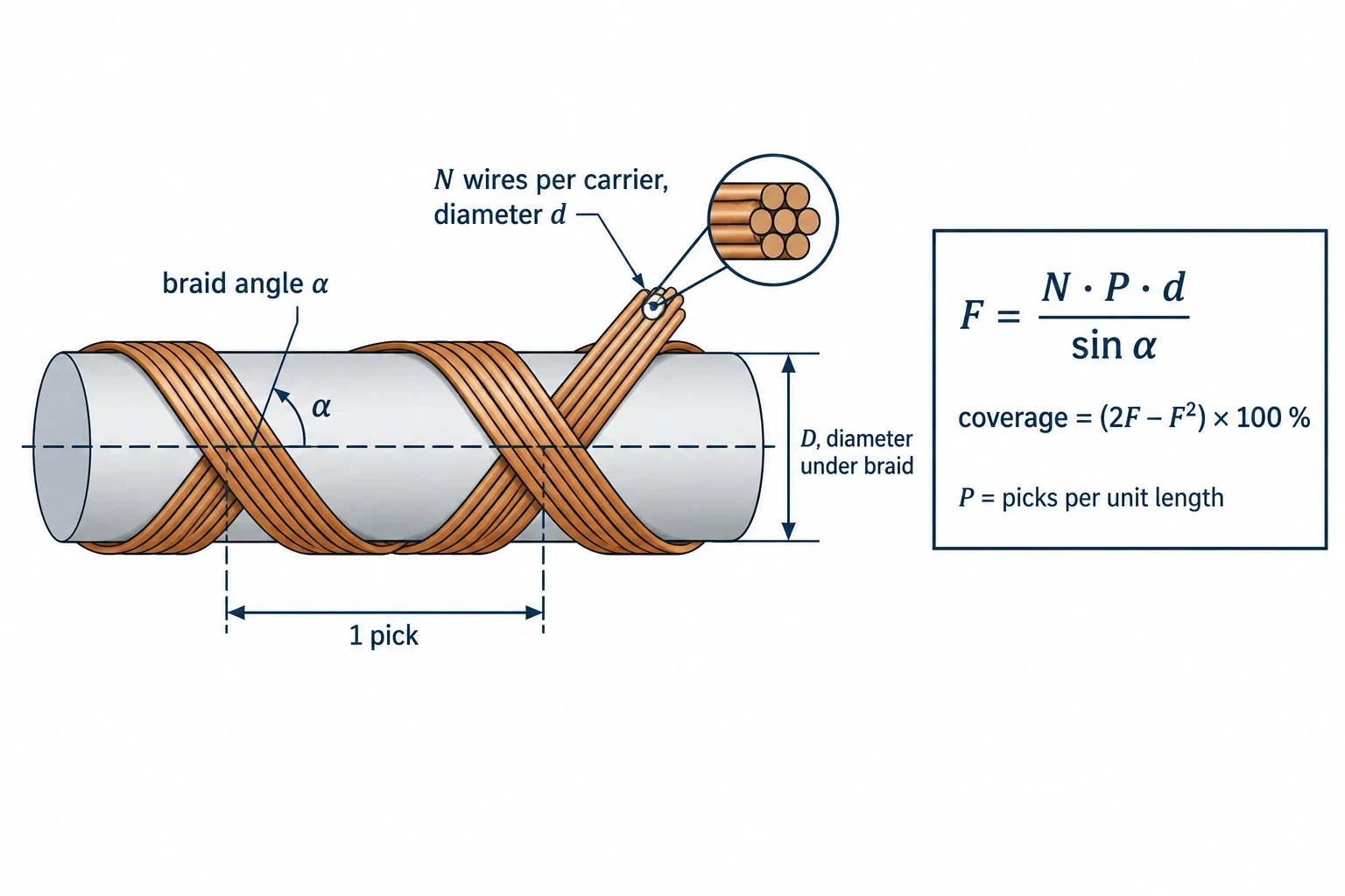
Braid coverage is the percentage of the core that the braid wires cover optically, calculated from the core diameter, wire diameter, number of carriers, wires per carrier and picks per unit length. It states how much of the surface is metal; it does not by itself state how well the screen performs, and it cannot be read off a photograph.
The calculation is old and standardised. ANSI/SCTE 51 2018 (R2024), Method for Determining Drop Cable Braid Coverage, defines coverage as the percentage of optical coverage of the core by the braid wires and names exactly those five inputs. The usual form of the arithmetic works in two steps: a fill factor F = N · P · d / sin α, where N is the number of wires per carrier, P the picks per unit length, d the wire diameter and α the braid angle; then coverage = (2F − F²) × 100 %. The braid angle itself follows from the diameter under the braid, the picks and the number of carriers. Two braids can reach the same percentage with very different wire counts and angles, which is why a coverage figure without the construction behind it is only half a specification.
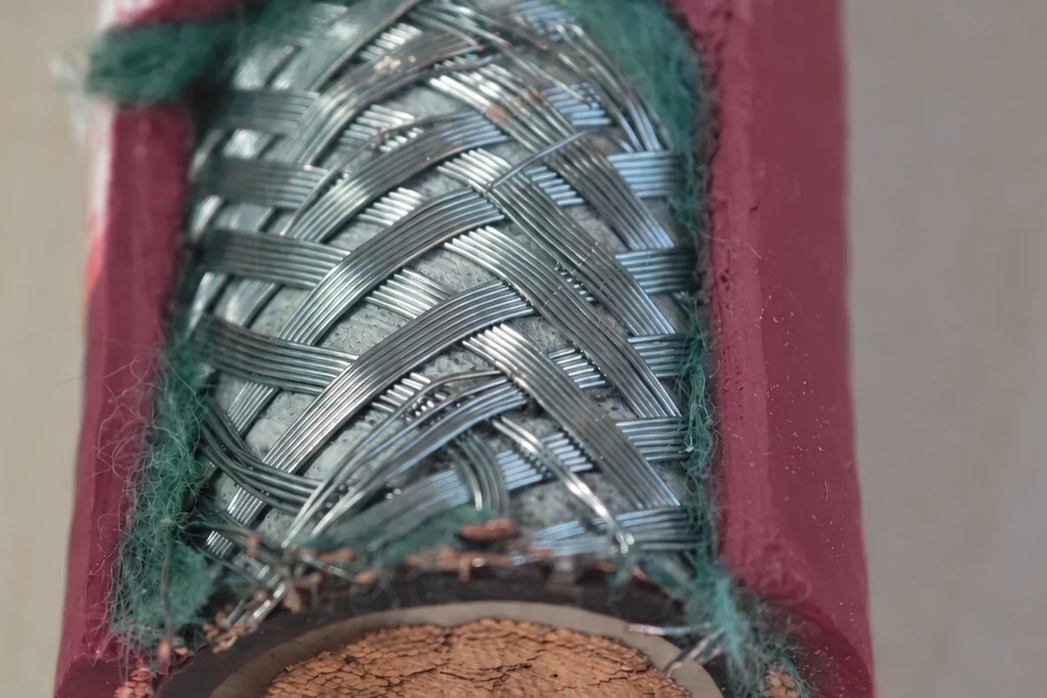
Three things to keep straight when a datasheet quotes coverage. First, 100 % is unobtainable with a braid; distributor technical guides put the common range at roughly 75 % to 85 %, with 90 % to 96 % available at a cost in copper, speed and flexibility. Second, TEBAOFLEX states coverage where the product record supports it: the (N)GRDGCGÖU-J festoon cable carries a tinned copper wire braid with more than 80 % coverage, and the screened C-PUR-HF option of the Festoonflex crane cable uses approximately 85 % tinned copper braid over the PUR inner sheath. The two samples photographed for this article are not quoted with a coverage figure because a photograph is not a calculation. Third, coverage is a geometric statement, while EMC performance is measured: surface transfer impedance to IEC 62153-4-3 (triaxial method) and screening attenuation to IEC 62153-4-4. A specification that needs a screening performance should ask for those figures; one that needs a fault-current path should ask for the screen’s copper cross-section. Coverage alone answers neither.
Tinned copper: material choice vs shield construction
Tinned copper is a material description, not a construction: it means annealed copper wire with a thin tin coating, as specified in ASTM B33 for tin-coated soft copper wire, and it can be served or braided equally well. The tin protects the wire against corrosion and oxidation and keeps it solderable, which matters at the termination; it does not change how the wires are laid.
The confusion is understandable because supplier chat and datasheets both tend to lead with the material. “Tinned copper braid” and “tinned copper serve” share the first two words and differ in the one that matters for flexing and frequency. Read them as two separate facts. The material answers: will the screen still terminate cleanly after five years in a damp shaft or a salt-laden port? Tin says yes; bare copper says it depends. The construction answers: will the screen still be closed after five years of bending? That is the serve-versus-braid question, and tin has no opinion on it. Bare copper serves and braids exist and are cheaper; silver-plated and nickel-plated wires exist for high-temperature screens. The choice of coating follows the environment and the termination method, and it is made independently of the choice between a serve and a braid.
From serving line to finished cable
A served screen is applied on a serving line: the insulated core passes through a rotating head that pays off the copper wires from bobbins and lays them at a set angle as the core advances, so the lay length and the wire count fix the coverage. A braid is applied on a braider, whose carriers travel in two interlocking tracks around the core so the wire groups pass alternately over and under each other. The finished layers look different because the machines move differently.
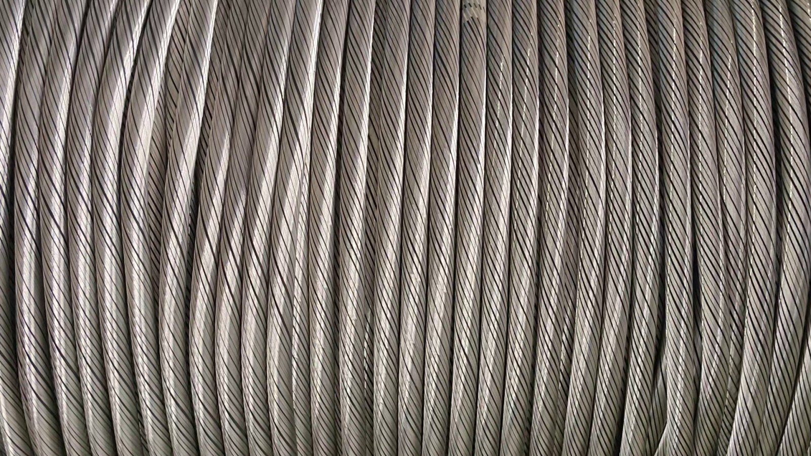
The still below is from the TEBAOFLEX line, taken from a short video of served single cores being taken up on a reel before sheathing. The helical lay is visible on every core, all at the same angle and direction; the parallel bright lines are the tinned wires, and there are no crossings. After serving, the core goes to the extruder for the sheath that will hide all of this from everyone except the person who cuts the cable open.
The same clip shows where the lay angle is set. The core runs through the centre of a rotating serving head; the tinned wires pay off bobbins behind it and converge on the core at the die, and the ratio of head speed to line speed fixes the lay length, and with it the coverage.
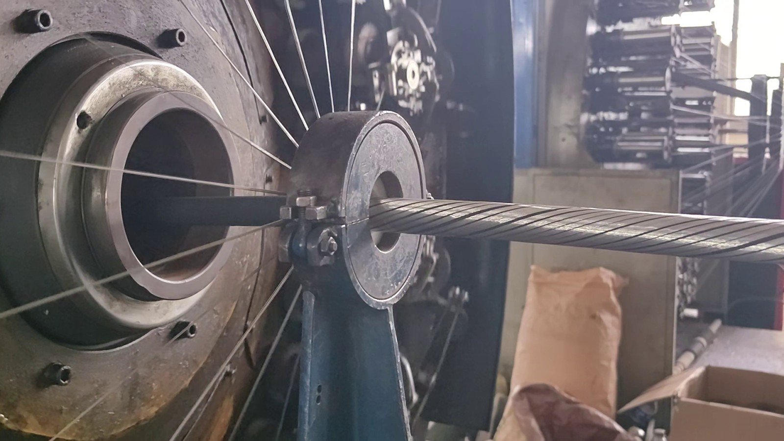
Why show this at all? Because “screened” on a quotation is a claim about a process the buyer never sees. A serving head cannot produce a braid, and a braider cannot produce a serve, so the machine on the line settles which construction is in the cable more reliably than the adjective on the datasheet. When a specification matters, ask which line the screen came off.
Where each construction appears in industrial cable
In industrial and power cable the two constructions have settled into different jobs. Served copper wires form the concentric screens and protective wires of flexible medium-voltage cores, where the screen’s job is charging and fault current at power frequency and the core must bend. Braids form the overall EMC screens of drive and festoon cables and, as composite copper-and-textile braids, the individual core screens of mining trailing cables, where coverage must survive dragging. The construction standards leave the choice open on purpose: IEC 60502 allows the metallic screen of a power cable to consist of one or more tapes, a braid, a concentric layer of wires, or a combination of wires and tapes, and sizes it by copper cross-section for fault current rather than by coverage.
The TEBAOFLEX range shows the split. The (N)TMCGC11Y switchgear cable puts spirally applied tinned copper protective wires over EPR insulation and semiconductive layers for 6/10 kV to 18/30 kV links that are trained around equipment. The (N)SSHCÖU VFD mining cable uses individually screened cores and an EMC-optimised concentric braid of tinned copper wires for converter-to-motor circuits. The Type 209 mining cable screens each power core with a tinned copper and polyamide braid, and the SHD-GC mining cable combines conductor and insulation shielding with a composite tinned copper and polyamide braid on each core, the construction that the S in its name stands for, as explained in what type SHD means in mining cables.
The clearest illustration of the mechanical trade-off is not a screen at all. On the (N)SSHCGEÖU low-tensile cutter cable the concentric earth conductor is a reinforced spiral of copper and steel wires, chosen because it tolerates very tight repeated bending; the high-tensile sister construction uses a copper-steel tensile braid instead, which carries pull but will not follow the same radius. Same conductor job, two constructions, chosen by whether bending or tension governs. That is the whole serve-versus-braid decision in one product family.
Two things that look like screens are not. A braided layer of galvanised steel wires, as on an armoured monitored mining cable, is armour: it is there for mechanical protection and may be earthed, but it is not designed as a screen. A helically laid steel armour on a wireline or an armoured offshore cable is likewise a mechanical layer, and the RFOU vs BFOU guide explains how a braided armour differs from a screen on marine cables. Whether a layer is served or braided tells you how it is made; whether it is a screen or an armour tells you what it is for, and the two questions have to be answered separately.
What to specify when ordering a shielded cable
Specify the screen by its job, its construction and the figure that proves it, in that order: state what the screen must do (EMC, fault current, monitoring), name the construction if an existing drawing fixes it (served wires, braid, composite braid, tape), and ask for the coverage or the screen cross-section that the job requires, plus transfer impedance where drive-frequency EMC is specified.
- State the cable designation or send the drawing. If a designation such as (N)SSHCÖU or SHD-GC already fixes the screen construction, say so; do not ask a braided design to be quoted as a serve or the reverse without an engineering reason.
- State the application and the circuit: fixed feeder, switchgear link, converter-to-motor, festoon, reeling or trailing, and the voltage class.
- State the movement: fixed, occasional handling, continuous flexing with the bend radius, drum diameter and travel speed, or dragging across the floor. This is what decides between a serve, a braid and a composite braid.
- State the screen requirement in the form the project uses: minimum optical coverage in percent, screen copper cross-section in mm² for fault current, or transfer impedance and screening attenuation to IEC 62153-4-3 / 62153-4-4 for EMC.
- State the conductor size and count, the earth or pilot arrangement, and how the screen will be terminated, because a 360° EMC gland and a pigtail want different constructions.
- State the required length and the reel or coil packing.
Send those six items and the engineering team can confirm whether the construction on the drawing matches the duty, or propose the one that does, before anything is quoted.
Buying questions before the first screened cable order
Can we order a trial length of a screened construction?
The minimum order quantity is 50 m as of August 2026, and it is the same for standard and customised constructions, so a trial length of a served or braided cable does not carry a premium. Confirm the current minimum when you enquire, since it is reviewed periodically.
How long does a screened cable take to produce?
Standard lead time runs 7 to 45 working days as of August 2026, depending on product type, stock position and how much of the construction is customised. A braided screen adds a production step to a served one; confirm current timing with the engineering team before you commit it to a shutdown or delivery window.
Which certificate covers the screen?
None of the TEBAOFLEX certificates is a screening-performance certificate. The VDE Marks Approval, certificate 40060056 issued 2025-03-28, covers cross-linked elastomer insulated flexible cables to DIN EN 50525-2-21 (VDE 0285-525-2-21):2012-01 / EN 50525-2-21:2011; the UL 62 and CSA C22.2 No. 49 certificates cover flexible cord.
Screen coverage, copper cross-section and, where required, transfer impedance are documented per construction, so state in the enquiry which figure and which test report your project needs and the engineering team will confirm what can be supplied.
Questions
Is a serve shield the same as a spiral shield?
Yes. Serve shield, spiral shield and served screen are three names for the same construction: copper wires laid side by side in one helical direction with no interweaving. A reverse spiral is a variant with two served layers in opposite directions, still without interweaving, and it is not a braid.
Can both spiral and braided shields use tinned copper?
Yes. Tinned copper describes the wire, not the layout, and it is used for served and braided screens alike, as the two factory samples in this article show. The coating decides corrosion resistance and solderability at the termination; the serve-or-braid choice decides flexing behaviour and frequency performance, and the two decisions are made separately.
Can a spiral shield replace a braided shield in an existing cable specification?
Not on appearance alone. A serve can match a braid’s optical coverage on paper while behaving differently under tension and at drive frequencies, and an EMC gland sized for a braid may not clamp a serve. Check the coverage, screen cross-section or transfer impedance the original specification calls for, and the movement the cable sees, before accepting a substitution.
Is a shield the same as an armour?
No. A shield or screen is an electrical layer, served or braided from copper, that carries charging, fault or interference current to earth. An armour is a mechanical layer, usually galvanised steel wires, braided or helically laid, that protects the cable against crushing and pulling; it may be earthed but it is not designed as a screen.
Send the specification, not just the word “screened”
Cut the sample open if you can; the wires will tell you in a second whether you are holding a serve or a braid. Then send TEBAOFLEX the cable designation or drawing, the application, the movement conditions, the screen requirement in the form your project uses, the conductor size and the required length, and the engineering team will confirm the construction and the current lead time for the cable that fits.